AW00097603000 Physical Interface
Basler aviator GigE 31
5 Physical Interface
This chapter provides detailed information, such as pinouts and voltage requirements, for the
physical interface on the camera. This information will be especially useful during your initial
design-in process.
5.1 General Description of the Camera
Connections
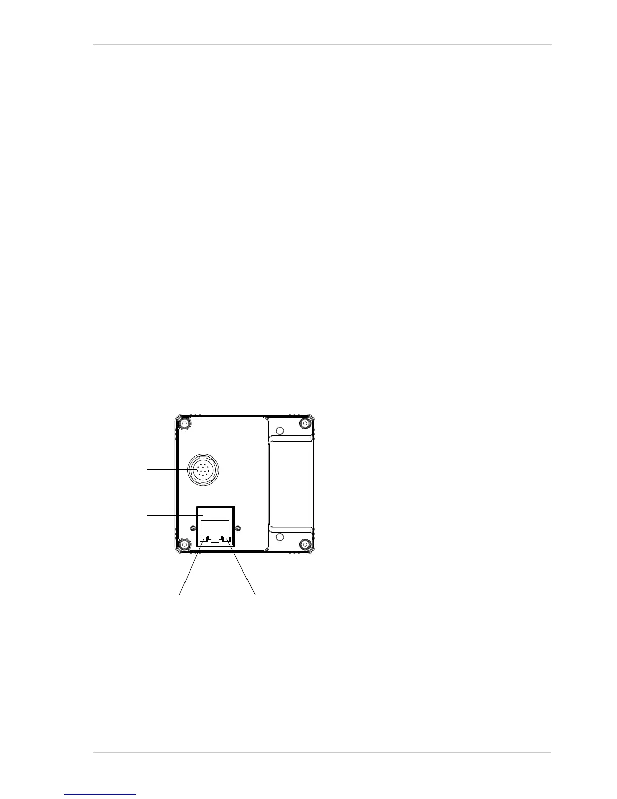
The camera is interfaced to external circuity via connectors located on the back of the housing:
An 8-pin, RJ-45 jack used to provide a 100/1000 Mbit/s Ethernet connection to the camera.
A 12-pin receptacle used to provide access to the camera’s I/O lines and to provide power to
the camera.
Figure 10 shows the location of the two connectors.

 Loading...


