Physical Interface AW00097603000
32 Basler aviator GigE
5.2 Camera Connector Pin Assignments
and Numbering
5.2.1 12-Pin Receptacle
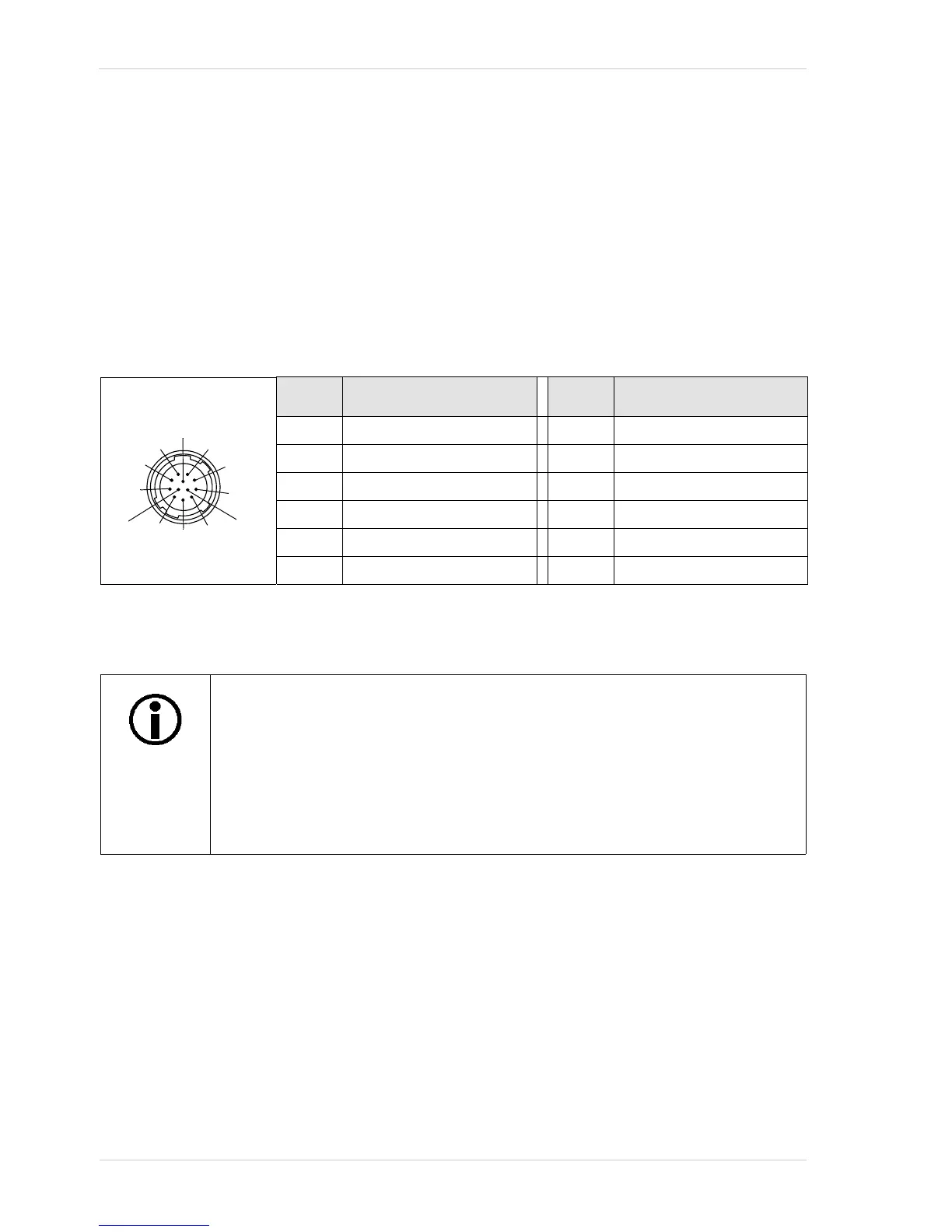
The 12 pin receptacle is used to access the two physical input lines and four physical output lines
available on the camera. The pin assignments and pin numbering for the receptacle are as shown
in Table 1.
5.2.2 8-Pin RJ-45 Jack
The 8-pin RJ-45 jack provides Ethernet access to the camera. Pin assignments adhere to the
Ethernet standard.
Pin Designation Pin Designation
1 Camera Power Gnd * 7 I/O Output 2
2 Camera Power Gnd * 8 Camera Power VCC **
3 I/O Input 1 9 Camera Power VCC **
4 I/O Input 2 10 I/O Output VCC
5 I/O In Ground 11 I/O Output 3
6 I/O Output 1 12 I/O Output 4
Table 1: Pin Assignments and Numbering for the 12-pin Receptacle
* Pins 1 and 2 are tied together inside of the camera.
** Pins 8 and 9 are tied together inside of the camera.
To avoid a voltage drop when there are long wires between your power supply and
the camera, we recommend that you provide +12 VDC camera power through two
separate wires between the power supply and pins 8 and 9 in the receptacle. We
also recommend that you provide camera power ground through two separate
wires between the power supply and pins 1 and 2.

 Loading...


