EasyManuals Logo

Basler GigE CAMERAS User Manual

Basler GigE CAMERAS
326 pages
To Next Page IconTo Next Page
To Previous Page IconTo Previous Page
Page #49 background imageLoading...
Page #49 background image
AW00097603000 Physical Interface
Basler aviator GigE 39
5.7.2 Characteristics
The camera is equipped with two physical input lines designated as input line 1 and input line 2.
The input lines are accessed via the 12-pin receptacle on the back of the camera.
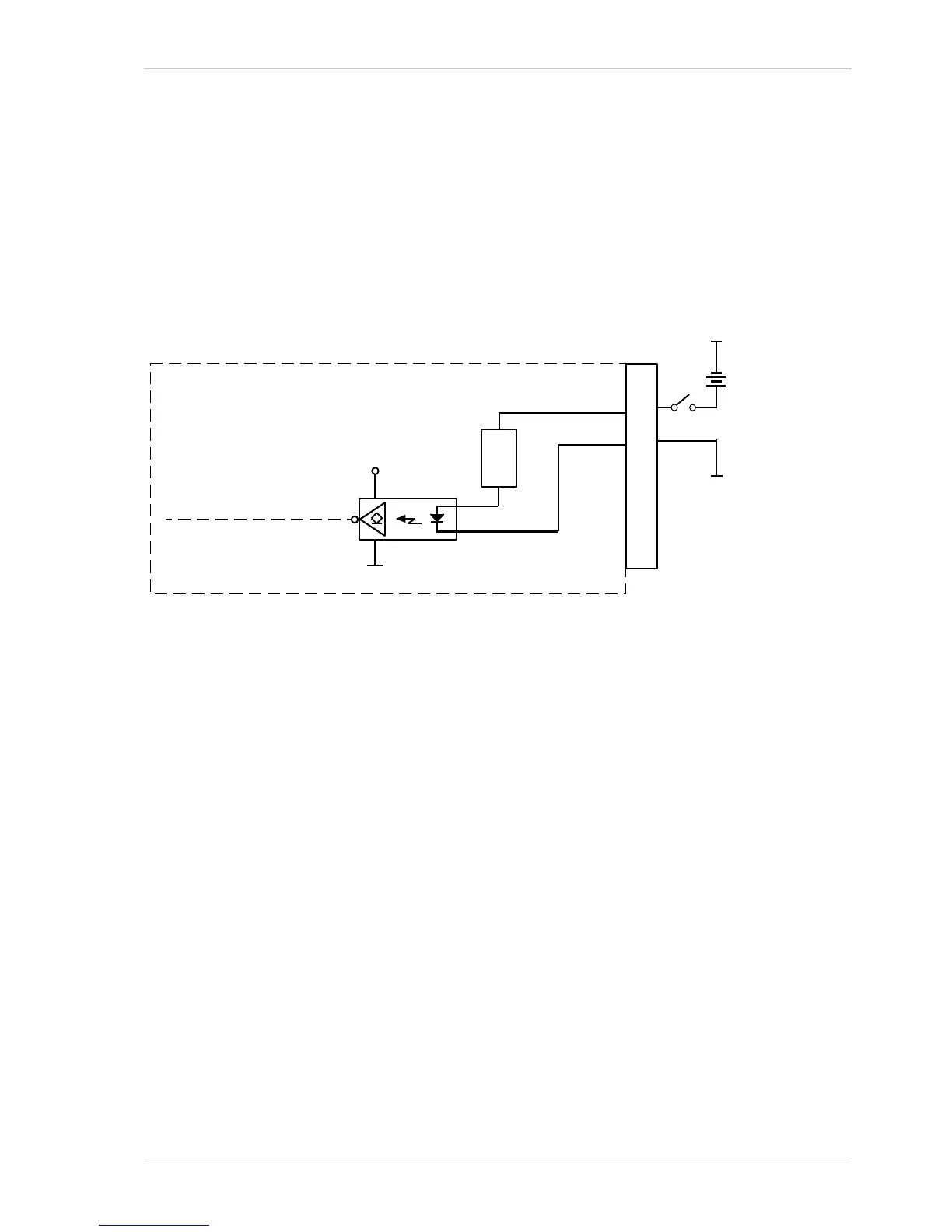
As shown in the I/O line schematic, each input line is opto-isolated. See the Voltage Requirements
section for recommended input voltages and their significances. The current draw for each input
line is between 5 and 15 mA.
Figure 12 shows an example of a typical circuit you can use to input a signal into the camera.
For more information about input line pin assignments and pin numbering, see Section 5.2 on
page 32.
1
2
3
4
5
6
7
8
9
10
11
12
I/O In 1
In 1 Ctrl
I/O In Gnd
12-Pin
Receptacle
Your
Gnd
Your
Gnd
Input
Voltage
+0 to 24
VDC
Camera
Fig. 12: Typical Input Circuit (Simplified)
Current
Limiter

Table of Contents

Questions and Answers:

Question and Answer IconNeed help?

Do you have a question about the Basler GigE CAMERAS and is the answer not in the manual?

Basler GigE CAMERAS Specifications

General IconGeneral
BrandBasler
ModelGigE CAMERAS
CategoryDigital Camera
LanguageEnglish

Related product manuals