MX680RD User’s Manual
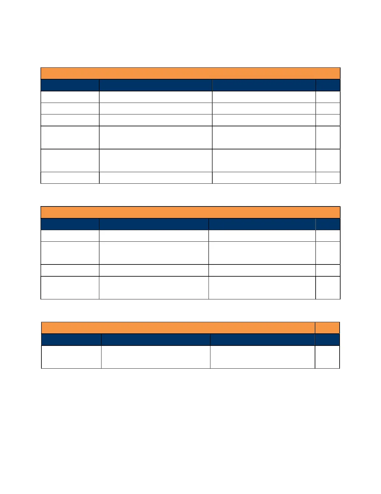
1.4.3 Layout Content List
• 1.4.3.1 Slots
Label Function Note Page
SODIMM_A1 262-pin DDR5 SODIMM slot 1 32MB maximum per slot 34
SODIMM_B1 262-pin DDR5 SODIMM slot 2 32MB maximum per slot 34
M2E1 M.2 Key-E Slot (2230) Supports PCIe x1, USB2.0, CNVi 41
M2M1 M.2 Key-M Slot (2242/ 2280)
(Top Side)
Supports PCIe x4, SATA 41
M2M2 M.2 Key-M Slot (2280)
(Bottom side)
Supports PCIe x4, SATA 41
PCIEX16_1 PCIe x16 slot Supports PCIe x16 (Gen 5) 53
• 1.4.3.2 Internal Jumpers
Label Function Note Page
CLCMOS1 Clear CMOS 1 x 3 header, pitch 2.00mm 51
JPSON1 ATX/AT Mode Select
(ATX Mode (default) / AT Mode)
1 x 3 header, pitch 2.00mm 49
JBKLVOL1 LVDS Panel Voltage Selection 1 x 3 header, pitch 2.00mm 49
JLVDS_BKL1 LVDS Brightness Control Mode
Selection
1 x 3 header, pitch 2.00mm 50
• 1.4.3.3 Dip Switch
Label Function Note Page
RI_SEL1 COM Mode Setting for COM1,
COM2
Provides slection between
5V, 12V, or Ringin (default)
50