MX680RD User’s Manual
1.9 Connectors/ Headers
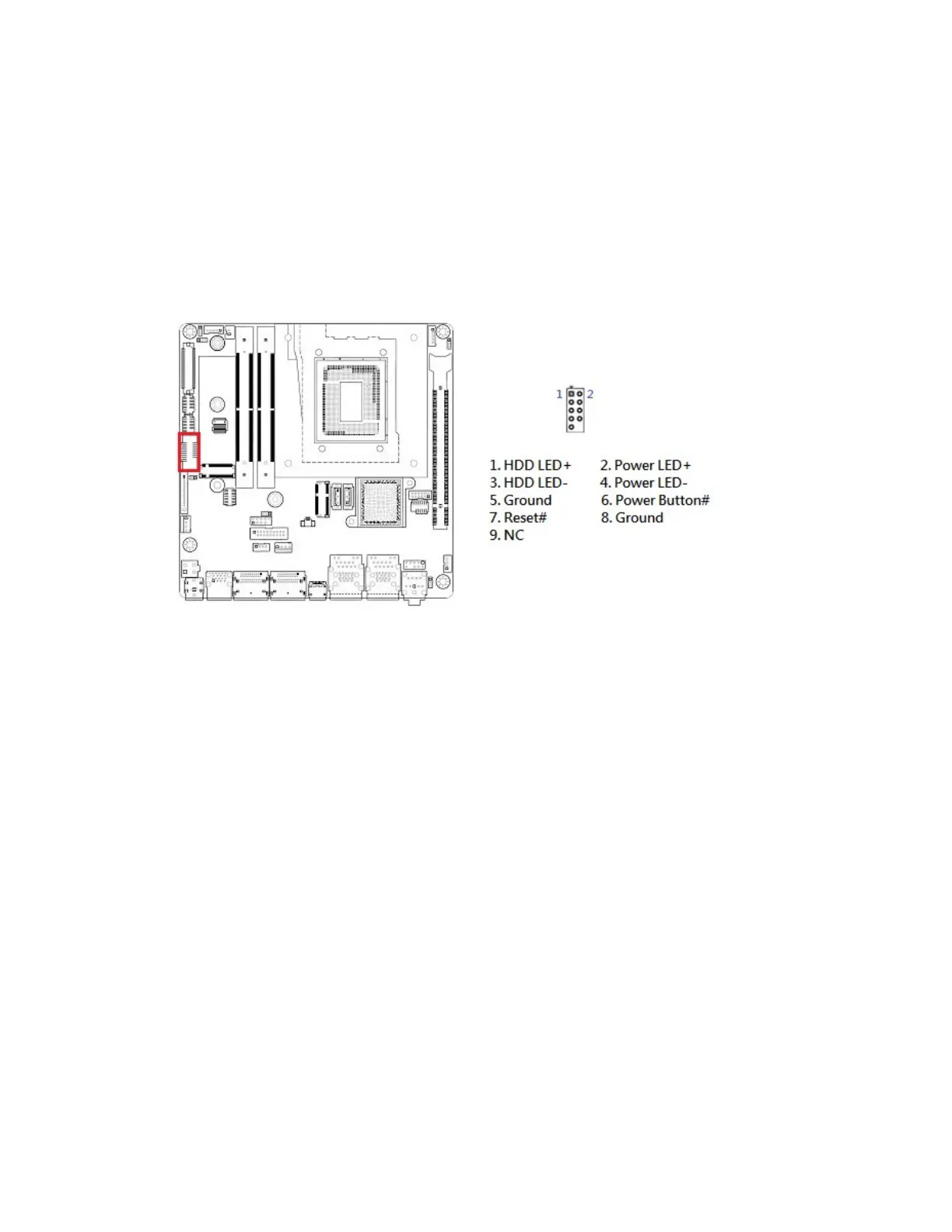
1.9.1 Front Panel Connector: F_PANEL1
These connectors are for electrical connections to the front panel switches and LEDs. The
“F_PANEL” connector is compliant with Intel® Front Panel I/O Connectivity Design Guide.
• Power Button/Soft-off Button (Pin 6-8)
This 2-pin connector is for the system power button. Pressing the power button turns the
system on or puts the system in sleep or soft-off mode depending on the BIOS settings.
Pressing the power switch and holding it for more than four seconds while the system is ON
turns the system OFF.
• Reset Button (Pin 5-7)
This 2-pin connector is for the chassis-mounted reset button for system reboot without turning
off the system power.
• Power LED (Pin 2-4)
This 2-pin connector is for the system power LED. Connect the chassis power LED cable to
this connector. The system power LED lights up when you turn on the system power, and
blinks when the system is in sleep mode.
• HDD LED (Pin 1-3)
This 2-pin connector is for the HDD Activity LED. Connect the HDD Activity LED cable to this
connector. The HDD LED lights up or flashes when data is read from or written to the HDD.