IPC@CHIP SC123/SC143
Hardware Manual V1.06 [18.02.2010]
©2000-2008 BECK IPC GmbH Page 13
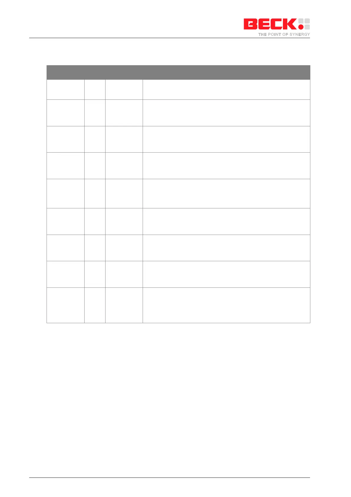
4.3 Chip Selects
Middle Memory Chip Select Output [8mA] (Active LOW)
This pin indicates an access to the internal SDRAM. (Do not
connect).
PCS[3]#
PCS[2]#
PCS[1]#
PCS[0]#
OUT [8mA]
OUT [8mA]
OUT [8mA]
OUT [8mA]
Peripheral Chip Select Output (Active LOW)
These pins indicate to the system that a bus cycle is in progress to
the corresponding region of the peripheral space.
Peripheral Chip Select Output [4mA] (Active LOW)
This pin indicates to the system that a bus cycle is in progress to
address 0xE00 of the peripheral space.
It can also be used as PIO[5].
Peripheral Chip Select Output (Active LOW)
This pin indicates to the system that a bus cycle is in progress to
address 0x800 of the peripheral space.
It can also be used as PIO[4].
Peripheral Chip Select Output (Active LOW)
This pin indicates to the system that a bus cycle is in progress to
address 0xA00 of the peripheral space.
It can also be used as PIO[3].
Peripheral Chip Select Output (Active LOW)
This pin indicates to the system that a bus cycle is in progress to
address 0xC00 of the peripheral space.
It can also be used as PIO[2].
Upper Memory Chip Select Input (Active LOW)
This pin should ALWAYS be connected to UCSOUT#, except when
an additional external memory (NV-SRAM, Flash) is used (e.g. see
chapter 11.3).
Upper Memory Chip Select Output (Active LOW)
This pin should always be connected to UCSIN#, except when an
additional external memory (NV-SRAM, Flash) is used (e.g. see
chapter 11.3).
Flash Select
This pin is for selecting external memory. If this pin is high, the
internal flash is selected. When low, external memory can be
accessed
(E.g. see chapter 11.3).
Table 4-2: Pin Description of Chip Selects
Note 1: 5V tolerant