IPC@CHIP SC123/SC143
Hardware Manual V1.06 [18.02.2010]
©2000-2008 BECK IPC GmbH Page 31
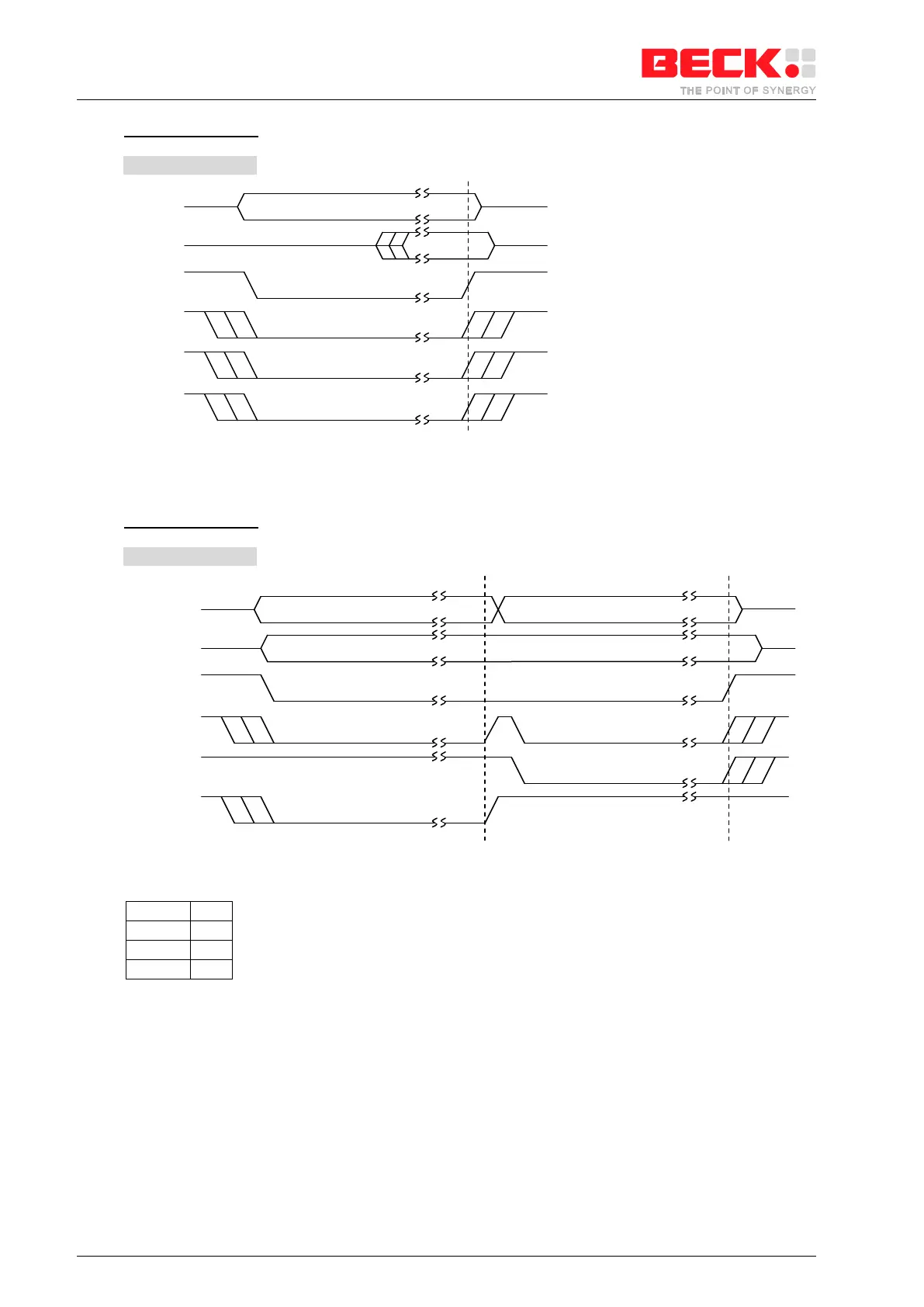
Word write to 0xC00
e.g.
Figure 6-13: 16 Bit write access to C00
h
, CSBE = 1, Write = 0x1234
Word write to 0xC01
e.g.
Figure 6-14: 16 Bit write access to C01
h
, CSBE = 1, Write = 0x5678
Result: