IPC@CHIP SC123/SC143
Hardware Manual V1.06 [18.02.2010]
©2000-2008 BECK IPC GmbH Page 60
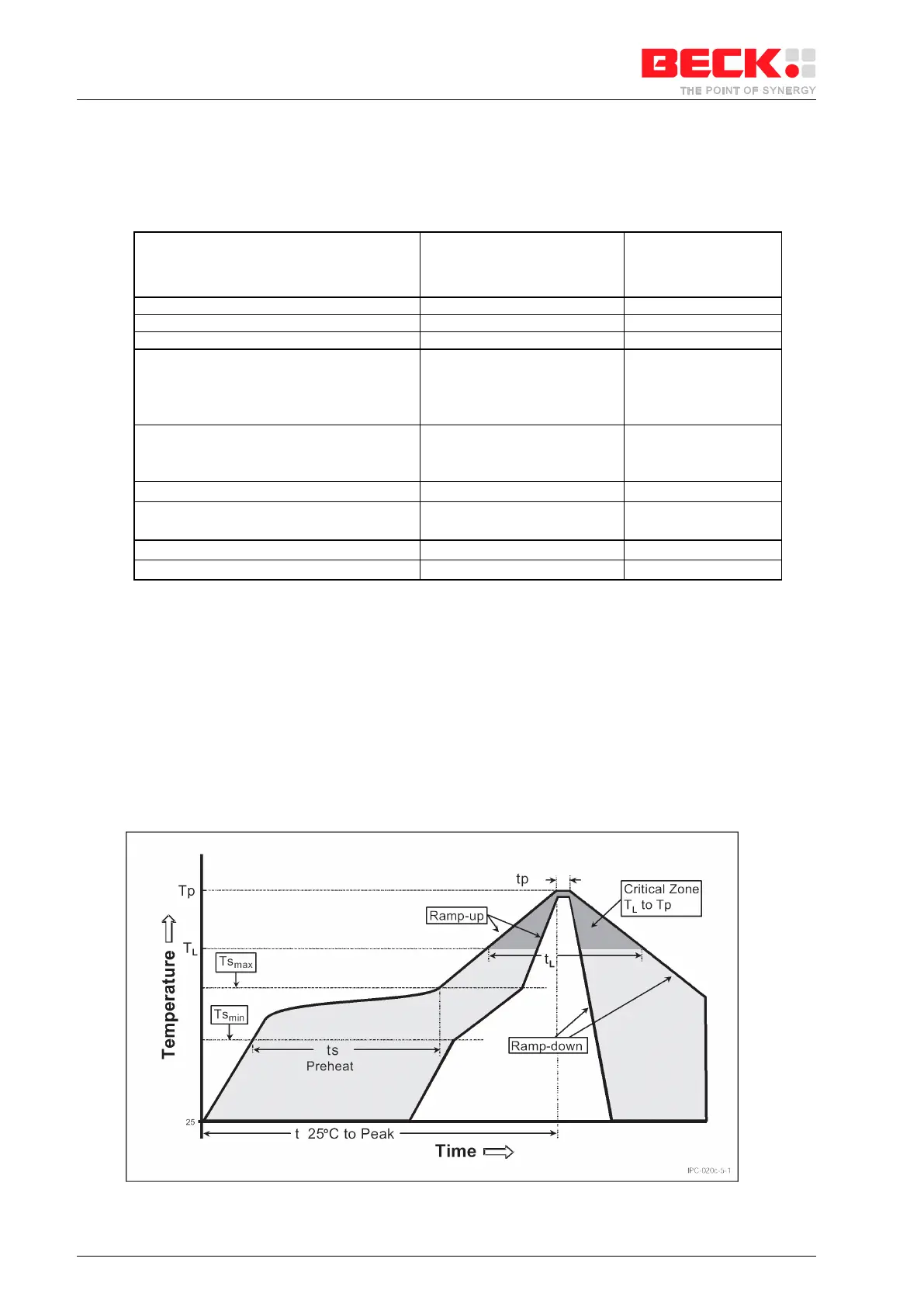
13 Reflow Profile
Typical Convection Reflow
SC123
SC123-IEC
SC143
SC143-IEC
SC123-LF
SC123-IEC-LF
SC143-LF
SC143-IEC-LF
Average Ramp-Up Rate (T
Smax
to Tp)
Preheat
-Temperature Min (T
Smin
)
-Temperature Max (T
Smax
)
-Time (t
Smin
to t
Smax
)
100 °C
150 °C
60-120 seconds
150 °C
200 °C
60-180 seconds
Time maintained above:
-Temperature (T
L
)
-Time (t
L
)
Peak/Classification Temperature (Tp)
Time within 5 °C of actual Peak
Temperature (tp)
Time 25 °C to Peak Temperature
Table 13-1: Typical Reflow Profile Conditions
Notes:
1. All temperatures refer to the topside of the package, measured on package body surface.
2. This profile is used for the internal qualification of packages and only shows the times and temperatures our
packages are guaranteed to withstand. This should not be understood as a recommended profile for the board
mounting of our parts. Customers should optimize their board mounting reflow profiles by using their board
design, solder paste and flux selection etc.
3. PB-free devices cannot be solderd in a leaded process at lower temperatures due to the PB-free material of
the BGA balls. Devices with SnPb balls cannot be soldered in a Pb-free process at higher temperatures.
Figure 13-1: Reflow Profile