EasyManuals Logo

Beck IPC SC123 User Manual

Beck IPC SC123
61 pages
To Next Page IconTo Next Page
To Previous Page IconTo Previous Page
Page #57 background imageLoading...
Page #57 background image
IPC@CHIP SC123/SC143
Hardware Manual V1.06 [18.02.2010]
©2000-2008 BECK IPC GmbH Page 57
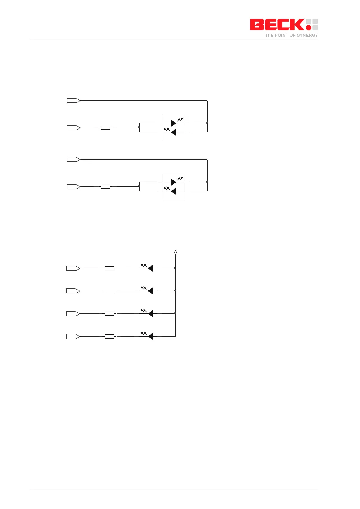
11.4 Traffic/Link/Speed LEDs
The following circuits are showing two different ways to connect LEDs to the SC1x3 for the status of ETH0.
Which of these circuits are valid can be chosen at system startup through a resistor at A[15], see chapter 5.2
Address Pins.
R1
100
R2
100
Duplex
yel
grn
D1
LED1
LED3
Link
yel
grn
D2
LED0
LED2
Figure 11-5: Circuit Example for two bi-coloured LEDs
yellow
10BaseT Link
green
100BaseT Link
yellow
Half Duplex Traffic
green
Full Duplex Traffic
R1
120
LED1
R2
120
D1
R3
120
100MBit Link
D3
R4
120
LED3
Link
Activity
Full Duplex
LED2
3.3V
LED0
D2
D4
Figure 11-6: Circuit Example for four mono-coloured LEDs

Table of Contents

Questions and Answers:

Question and Answer IconNeed help?

Do you have a question about the Beck IPC SC123 and is the answer not in the manual?

Beck IPC SC123 Specifications

General IconGeneral
BrandBeck
ModelIPC SC123
CategoryController
LanguageEnglish

Related product manuals