Operation
49
RCMS460-490_D00067_03_M_XXEN/12.2017
6.6 The main menu
6.6.1 Menu 1: Alarm/meas. values
RCMS…-D… displays the following for each measuring channel: alarm, measu-
red value, response value.
Column 1: Channel number 1…12
Column 2: Alarm status:
No alarm
Prewarning
Alarm, fault
Column 3: I(d): The currently measured r.m.s. value of the residual cur-
rent I
Δ
, the load current or the status of the digital input.
Column 4: I(dn): Set response value (rated residual operating current)
I
Δn
, digital input
or "Channel disabled“ or "CT connected“.
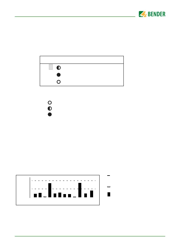
6.6.2 Menu 2: % Bar graph
For each of the 12 channels the RCMS…-D… shows the reached response va-
lue in per cent and/or the status of the digital inputs.
100 % Response value (alarm) resp. digital input = 1
50 % Prewarning (here set to 50 %)
0 % Channel disabled resp. digital input = 0
I(d) I(dn)
1. 4mA 10mA
2. 120mA 20mA
3.
Channel disabled
100%
50%
k 1 2 3 4 5 6 7 8 9
10
11
12
0%
Channel switched off
Channel enabled
Channel enabled,
current is flowing
(height ≥ 2 graduation m
(height = 1 graduation m