Operation
39
RCMS460-490_D00067_03_M_XXEN/12.2017
6.3 Working in operating mode
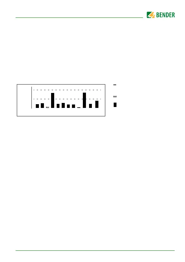
6.3.1 Standard display
In operating mode, you will see a bar graph on the RCMS460…-D display. For
each of the 12 measuring channels, it shows what percentage of the set alarm
value I
Δn2
(alarm) and I
Δn1
(prewarning) has been reached.
For digital inputs 100 % = 1 and 0 % = 0.
The RCMS…-L shows its BMS bus address (e.g. 02). Only the green "Power ON"
LED is lit.
6.3.2 Alarm and its effect
Possible causes of alarm messages:
The value falls below or exceeds the set response value or the prewarn-
ing threshold during current or residual current measurement.
Digital input closed resp. open
Fault measuring current transformer or CT connection fault
Device error (see „Display device error“ on page 82)
The RCMS460… signals prewarning and/or alarm:
LED "ALARM 1" (prewarning) and/or LED "ALARM 2" (alarm) light
depending on the type of alarm.
Associated common alarm relays (C…) switch.
RCMS490… only: Alarm relays of the individual channel switch.
An alarm message is being sent on the BMS bus.
100%
50%
k 1 2 3 4 5 6 7 8 9
10
11
12
0%
Channel disabled
Channel enabled
Channel enabled,
current is flowing
(height ≥ 2 graduation m
(height = 1 graduation m