47 support@solowavedesign.com
HardwareWood Parts
1 x Right Roof Board 1 x 4 x 30”
1 x Left Roof Board 1 x 4 x 30”
2 x Roof Support 2 x 2 x 29-1/4”
2109
6 x #8 x 1-1/2” Wood Screw
4 x #12 x 2” Pan Screw
S2
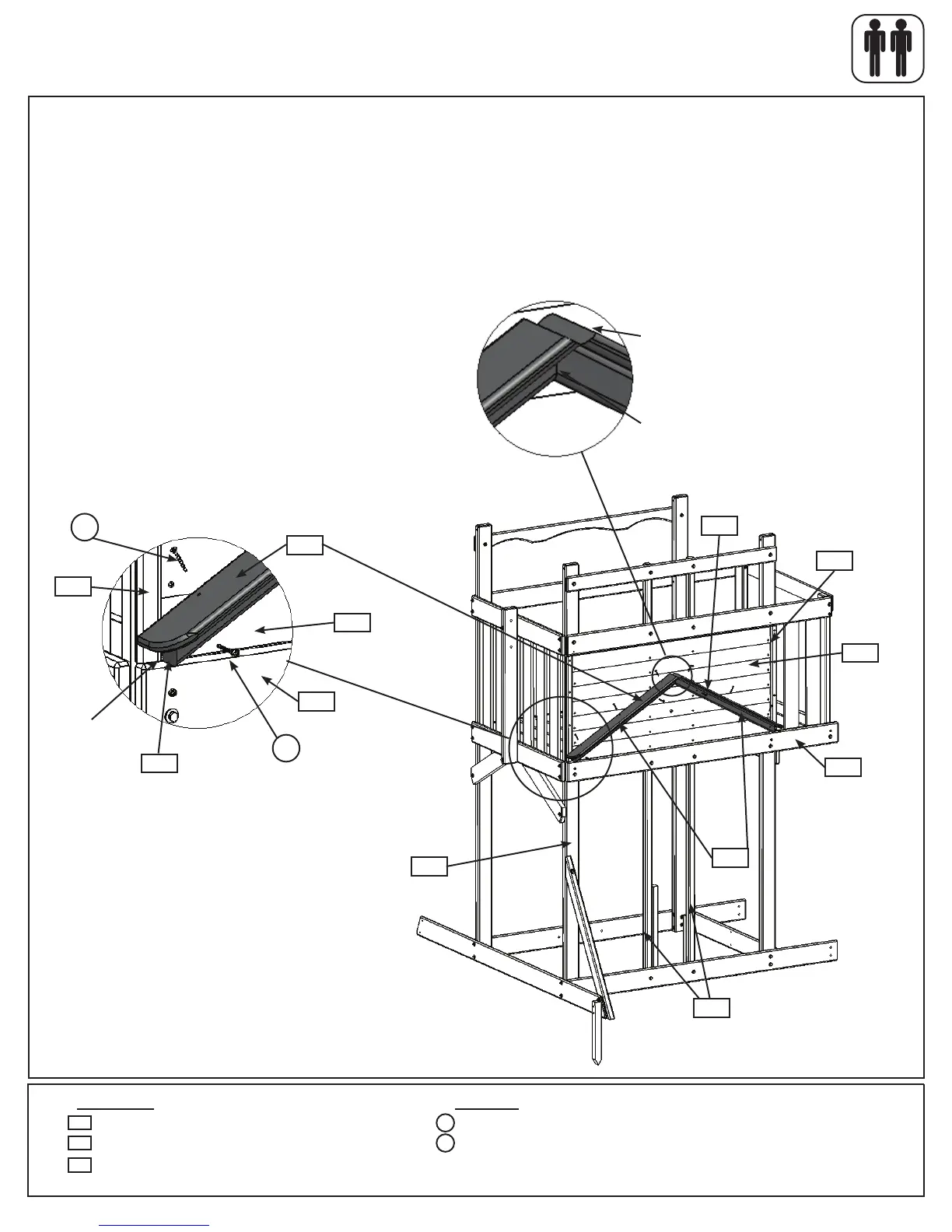
F: Place2(2152)RoofSupportsonthe(2128)Sidingsotheendsaretightagainsttheinsideedgesof(2118)
FrontTrimandtothetopof(2124)FrontFloor,asshowning.16.4and16.5.Thetopofthe(2152)RoofSup-
portsshouldformapeakandsittighttogether.Attachto(2153)Postsand(2154)FrontPostswith2(S7)#12x2”
PanScrewsineachsupport.(g.16.4,16.5and16.6)
G:Place(2108)LeftRoofBoardand(2109)RightRoofBoardontopof(2152)RoofSupportssotheymeettight
inthecentreandformapeak.Attachtoeach(2152)RoofSupportwith3(S2)#8x1-1/2”WoodScrewsper
board,asshowning.16.4,16.5and16.6.
Step 16: Upper Front Wall Assembly
Part 3
Fig. 16.5
2128
Fig. 16.6
Fig. 16.4
S7
S2
2118
Tight
2152
2108
x6
x4
Roofboardsushincentre.
Roofsupportsushincentre.
2152
2153
2154
2109
2128
2118
2152
2108
S7
2124
2124
Front Wall