USER MANUAL
TD069-O&M-001
REVISION 6
Page 24 of 80
Each module (QHPV & QEXT) is independently supplied with power. The QMTD is
supplied with power by the QHPV module.
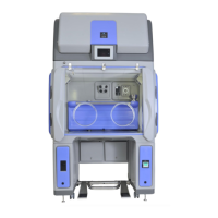
: Electrical connection plate
(QHPV)
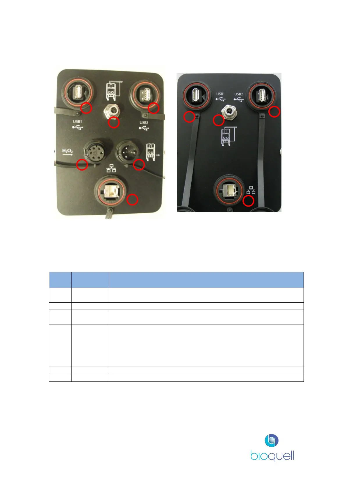
: Electrical connection plate
(QEXT)
The connection for the Glove Tester is located on the side of the QUBE left leg.
The connection for the viable monitor is located on the side of the QUBE right leg.
Link to internal USB connections for equipment being used
inside the chamber.
Duct pressure monitoring switch connection (ducted option)
Link to internal USB connections for equipment being used
inside the chamber.
A digital input has been provided for interfacing to a room gas
monitoring system by way of an external voltfree contact.
For this specification the input is present when the external
voltfree contact is closed. Item 4 provides the connection to the
room gas monitoring system. The equipment used must have a
Bulgin connector PX0800 with insert SA3243.