Project Configuration | 9
Bosch Motorsport Manual_C_80 35/144
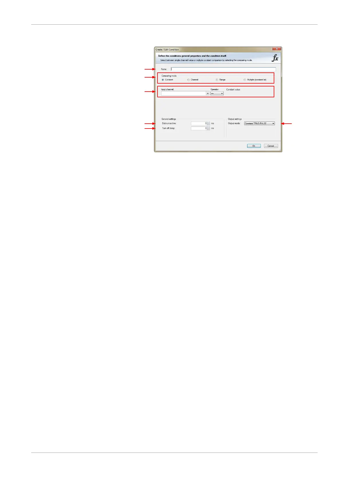
2. Define the condition channel, using the following configuration possibilities:
a) Enter the name of the conditional channel.
b) Select the comparing mode:
– Constant: Compare a measurement channel with a constant value.
– Channel: Compare a measurement channel with a measurement channel.
– Range: Compare a measurement channel with a defined value range.
– Multiple: Compare a measurement channel with up to 5 constant values.
c) Depending on the chosen comparing mode, you can enter the following values:
– Constant: Choose the measurement channel or condition, the operator and enter the
value of the channel.
– Channel: Choose the measurement channel or condition, the operator and the meas-
urement channel or condition to be compared.
– Range: Choose the measurement channel or condition, the operator and define the
minium and maximum value.
– Multiple: Choose the measurement channel or condition, the operator and enter the
value of up to 5 constants.
d) Enter the minimal time to detect the signal of the measurement channel, to avoid high-
frequent switchovers.
e) Enter the time by which the signal of the measuring channel is delayed after its end.
f) Choose the output setting of the result.
– Constant TRUE/FALSE: Result is as a constant with the value TRUE or FALSE.
– Blinking: Result is a blinking, if the condition is fulfilled.
– Pulse: Result is a short one-time pulse, if the condition is fulfilled.
– Toggling output: Result is a pulse that lasts until the next condition is fulfilled.
– Click ‘Ok’ when done. The conditional channel is displayed in the C 80 condition chan-
nel window.