EasyManuals Logo

Bosch C 80 User Manual

Bosch C 80
144 pages
To Next Page IconTo Next Page
To Previous Page IconTo Previous Page
Page #43 background imageLoading...
Page #43 background image
CAN Configuration | 10
Bosch Motorsport Manual_C_80 43/144
Payload Area
Row
Counter
Row
Counter
Payload Area
Message
Id
10.2 CAN input
10.2.1 Input configuration
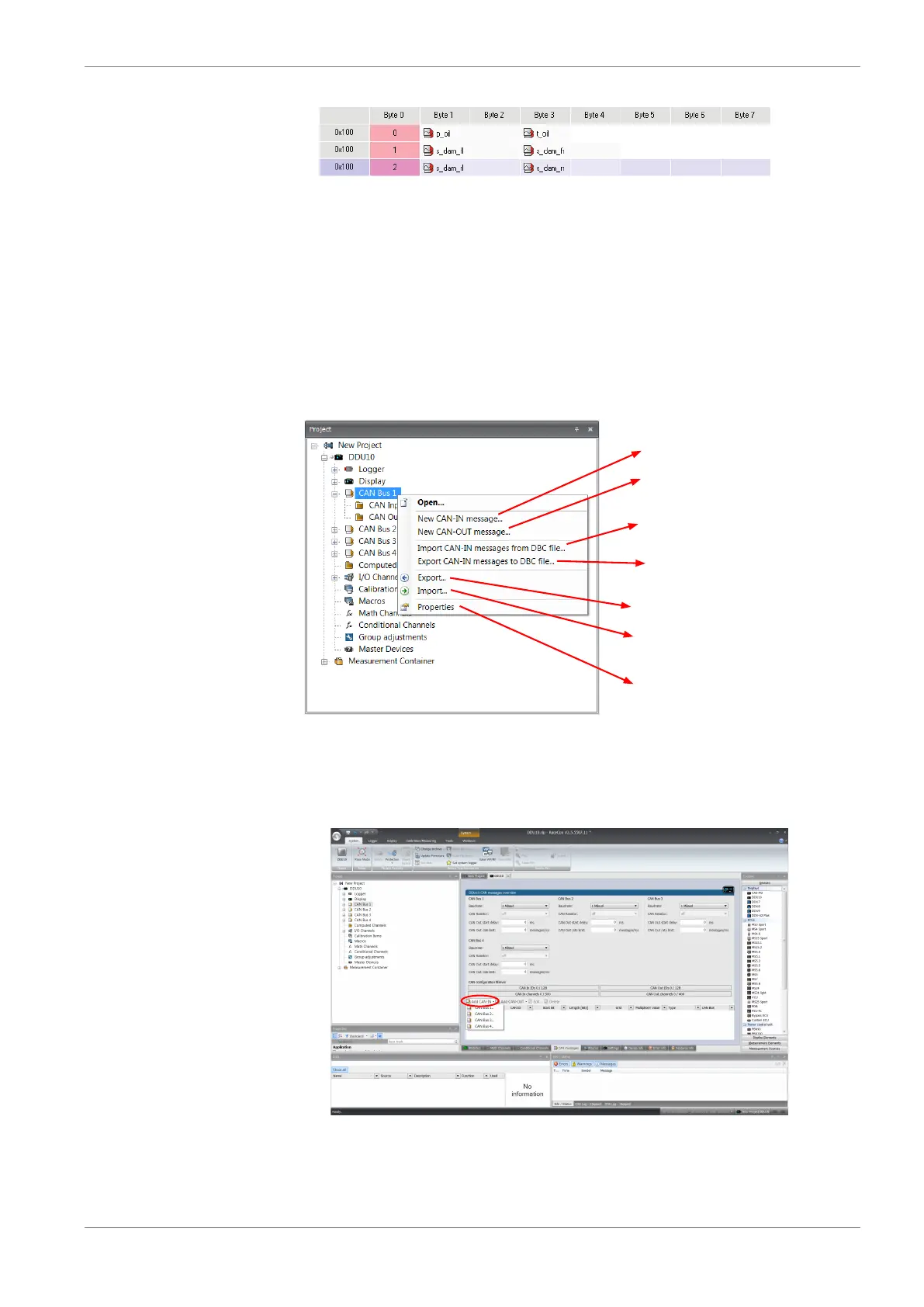
Click with the right mouse button on the desired CAN bus to open the CAN bus drop-
down menu.
Create new channel to read from CAN bus
Import Vector CAN database (DBC)
channel configuration
Export RaceCon CAN configuration to file
Import RaceCon CAN configuration from file
Display CAN bus properties (Baudrate)
Create new CAN output message
Export Vector CAN database (DBC)
channel configuration
10.2.2 Create new CAN Input channel
1. Double-click on any CAN bus item, to open the "CAN messages overview".
2. Select ‘Add CAN-IN’ and choose the desired CAN bus for the new input channel.
A CAN channel configuration window opens.

Table of Contents

Questions and Answers:

Question and Answer IconNeed help?

Do you have a question about the Bosch C 80 and is the answer not in the manual?

Bosch C 80 Specifications

General IconGeneral
Resolution16 bit
InterfacesUSB
Measurement Range±10V
Accuracy±0.1 % FS
Channels8 universal analog inputs (±10 V, ±20 mA, Pt100, Pt1000, Thermocouples type K, S, J, T, N, R, B, E), 4 digital inputs (trigger, counter, frequency), 2 digital outputs (24 V / 500 mA)

Related product manuals