3 | Onboard Network Concept
6/144 Manual_C_80 Bosch Motorsport
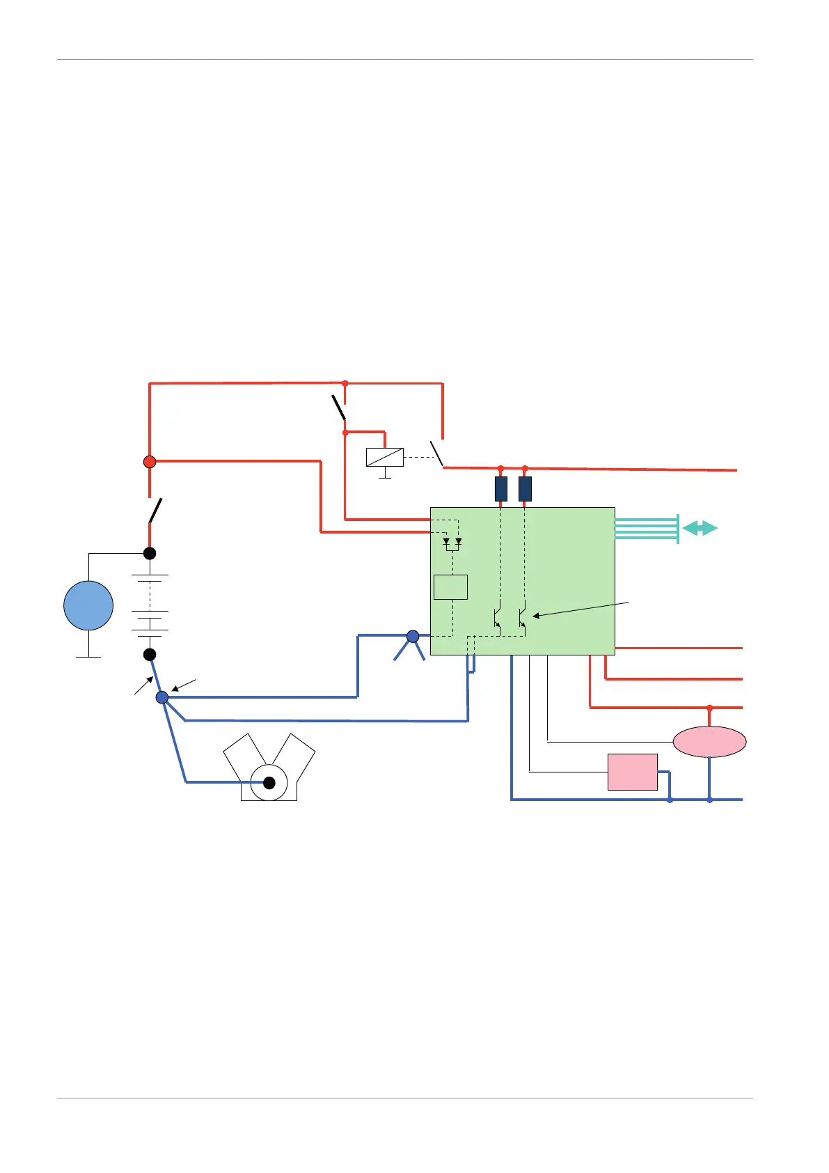
3 Onboard Network Concept
Please ensure that you have a good ground installation. That means:
– A ground that has a solid, low resistance connection to the negative battery terminal
– Connection should be free from dirt, grease, paint, anodizing, etc.
– Use large diameter wire
– More metal-to-metal contact is better!
The following notations for power signals are used:
– KL 15 is a switched battery rail controlled by the IGN-switch
– KL 30 is an unswitched battery positive rail (same as battery positive terminal)
– KL 31 is an unswitched ground rail (same as battery negative terminal)
Be careful to observe current limits of wires and connector pins!
G
Engine_GND
GND_Starpoint
Chassis
KL31
LS_GND_1
LS_GND_2
Main
Switch
UBAT
Star connection
(term30)
positive terminal
Electric Loads
IGN-
Switch
KL15
SENSPWR5
SENSGND
active
Sensor
ANA_IN(xx)
NTC
Sensor
ANA_IN(xy)
switched pos. terminal
Star connection
dig. sensors
(e.g. wheelspeed)
µC
As short as
possible
SENSPWR10
UBATT_FUSE
KL30
LS_SWITCH1…4
Bosch Motorsport
diagnosis connector
PC
Device
Note
This schematic is not device specific. Please see the section Technical Data for the specific-
ations of your device.