CAN Configuration | 10
Bosch Motorsport Manual_C_80 51/144
– Select the desired measurement channel and specify the message settings.
The measurement channel is now assigned to the CAN message.
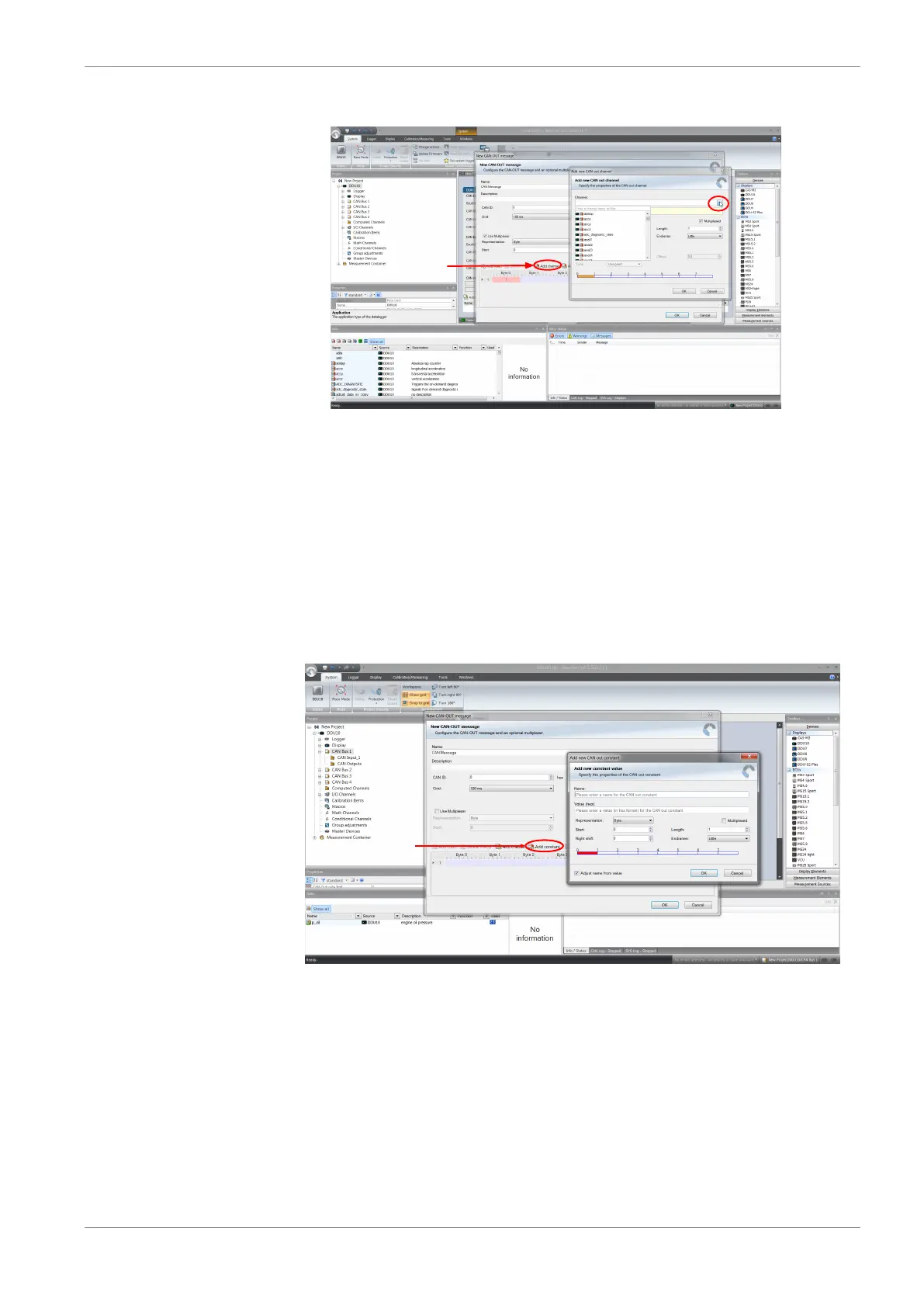
10.3.3 Add CAN out constant
To send a constant value on the CAN, perform the following steps:
1. Create a new CAN output message or edit an existing message.
2. Click ‘Add constant’. The ‘Add new CAN Out constant’ window appears.
3. Define the name of the constant, the required value in hex and define the CAN chan-
nel settings.
4. Click ‘OK’ when done.
10.4 Multiplexer
Row counter concept
If certain channel messages are not time-critical and can be imported or exported slowly,
you can use a multiplexer to put several channel messages on one message identifier.
– Re-use (multiplex) of message identifiers by splitting it into several rows.
– Every row is assigned to a unique value of the multiplexer.
– One byte of message contains row counter.