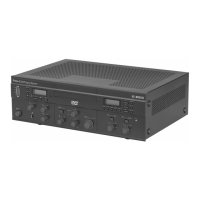
without errors (resulting in a 80 dB S/N ratio for the audio channels). The effect of the number
of carriers on the coverage area can be seen in the next two figures. The radiation pattern is
the area within which the radiation intensity is at least the minimum required signal strength.
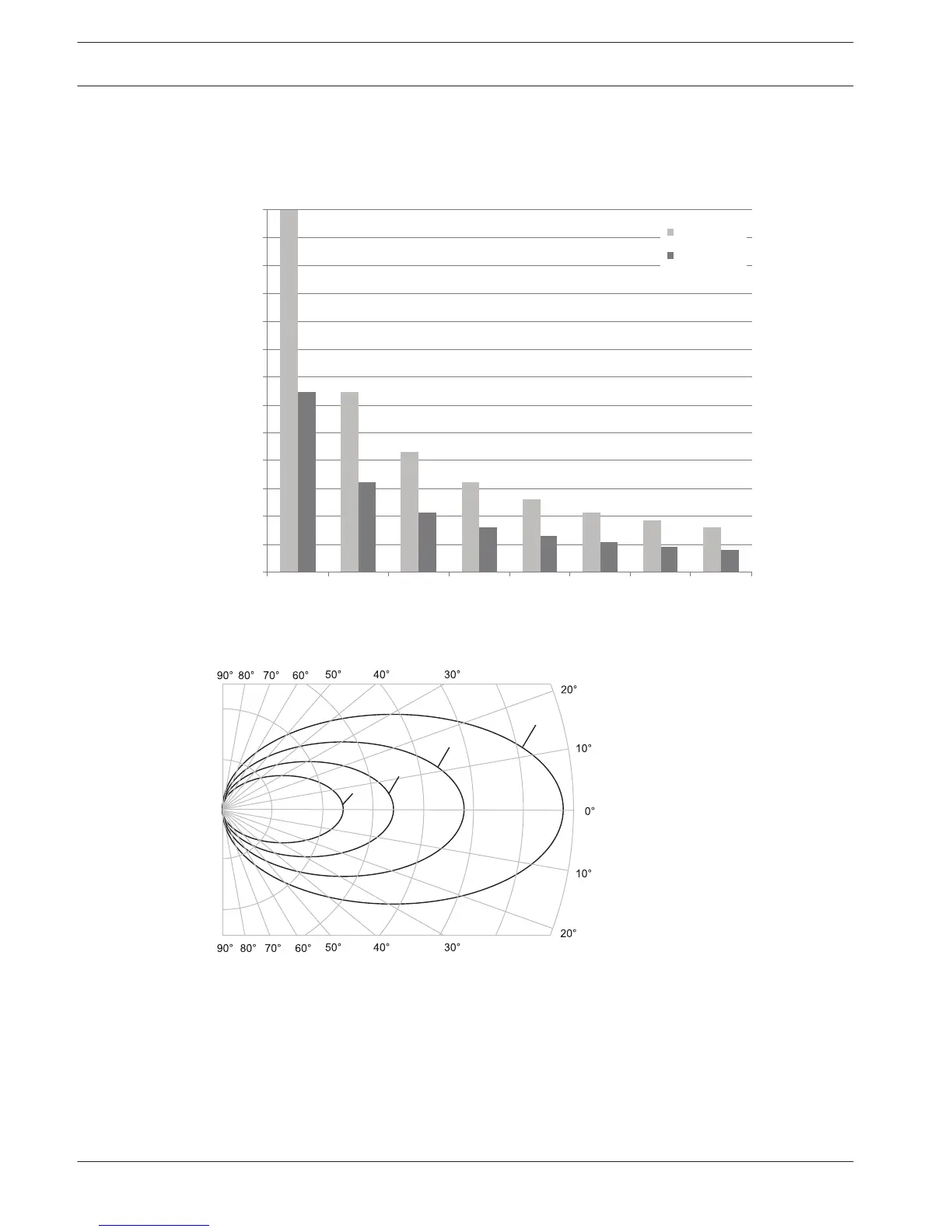
Figure 4.5: Polar diagram of the radiation pattern for 1, 2, 4 and 8 carriers
Footprint
The cross section of the 3-dimensional radiation pattern with the floor of the conference
venue is known as the footprint (the white area in the following three figures). This is the floor
area in which the direct signal is strong enough to ensure proper reception, when the receiver
is directed towards the radiator. As shown, the size and position of the footprint depends on
the mounting height and angle of the radiator.
24
en | Planning Language Distribution System
2013.11 | V1.4 | Operation manual Bosch Security Systems B.V.