Radiator
number
Trans-
mitter
Master-to-
slave signal
delay [ns]
Cable
signal
delay
[ns]
Total signal
delay [ns]
Signal delay
difference
[ns]
Delay switch
position
5 Master 0 280 0+280=280 593-280=313 313/33=9.48=9
6 Slave 313 168 313+168=481 593-481=112 112/33=3.39=3
7 Slave 313 280 313+280=593 593-593=0 0/33=0
8 Slave 313 112 313+112=425 593-425=168 168/33=5.09=5
9 Slave 313 168 313+168=481 593-481=112 112/33=3.39=3
10 Slave 313 280 313+280=593 593-593=0 0/33=0
Table 7.4: Calculation of the delay switch positions of a system with two transmitters
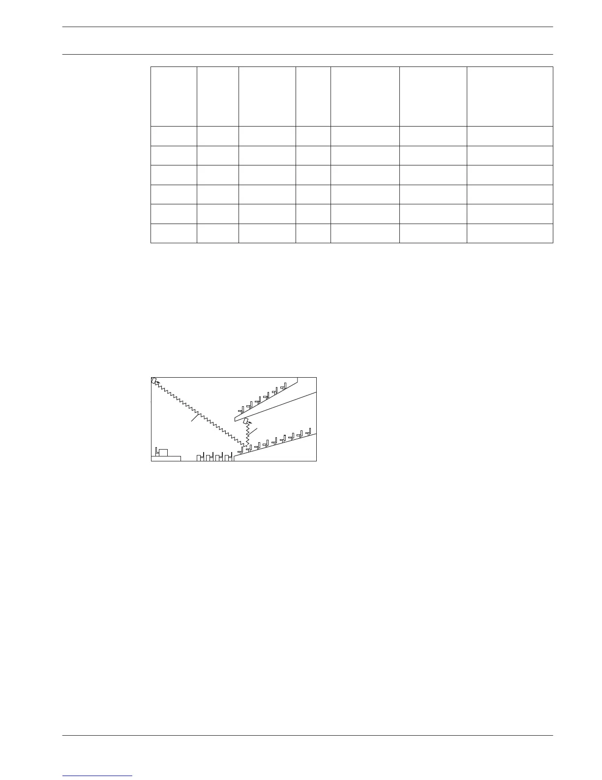
Systems with more than 4 carriers and a radiator under a balcony
The next figure illustrates a situation in which a radiation signal delay occurs and which can be
compensated for. For systems with more than four carriers, add one delay switch position per
10 meter (33 feet) difference in signal path length to the radiators which are closest to the
overlapping coverage area. In the next figure the signal path length difference is 12 meter. Add
one delay switch position to the calculated switch position(s) for the radiator(s) under the
balcony.
Figure 7.7: Radiation path length difference for two radiators
7.4.3
Language Distribution System Configuration | en 65
Bosch Security Systems B.V. Operation manual 2013.11 | V1.4 |