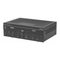
Radiator number Impulse res-
ponse time [ns]
Cable signal
delay [ns]
Signal delay
difference [ns]
Delay switch
position
1 350 350/2=175 292-175=117 117/33=3.64=4
2 584 584/2=292 292-292=0 0/33=0
3 237 237/2=118 292-118=174 174/33=5.27=5
4 339 339/2=169 292-169=123 123/33=3.73=4
5 563 573/2=281 292-281=11 11/33=0.33=0
Table 7.2: Calculation of the delay switch positions of a system with one transmitter
Notice!
The calculated delay switch positions based on impulse response time can differ from the
calculated delay switch positions based on cable lengths. This is caused by the accuracy of
the measurements and the accuracy of the cable signal delay factor per meter as specified by
the manufacturer of the cable. If the impulse response time is measured correctly, the
calculated delay switch positions will be the most accurate.
System with two or more transmitters in one room
When radiators in one multi purpose room are connected to two transmitters, an extra signal
delay is added by:
– Transmission from master transmitter to slave transmitter (cable signal delay).
– Transmission through the slave transmitter.
Use the following procedure to determine the delay switch positions in a master-slave
configuration:
1. Calculate the cable signal delay for each radiator, using the procedures for a system with
one transmitter.
2. Calculate the signal delay of the cable between the master and the slave transmitter in
the same way as for cables between a transmitter and a radiator.
3. Add to the cable signal delay of the cable between the master and the slave, the delay of
the slave transmitter itself: 33 ns. This gives the master-to-slave signal delay.
4. Add the master-to-slave signal delay to each radiator connected to the slave transmitter.
5. Determine the maximum signal delay.
6. Calculate for each radiator the signal delay difference with the maximum signal delay.
7. Divide the signal delay difference by 33. The rounded off figure is the signal delay switch
position for that radiator.
8. Add delay switch positions to radiators under a balcony, if applicable (see section
Systems with more than 4 carriers and a radiator under a balcony, page 65)
9. Set the delay switches to the calculated delay switch positions.