Notice!
For systems with a cable length difference of more than 50 meters, it is recommended to use
a measurement tool to determine the delay differences in order to calculate the delay switch
positions.
Determining delay switch positions by measuring the cable lengths
Use the following procedure to determine the delay switch position based on cable lengths:
1. Look up the cable signal delay per meter of the used cable. The manufacturer specifies
this factor.
2. Measure the lengths of the cables between the transmitter and each radiator.
3. Multiply the lengths of the cables between the transmitter and each radiator with the
cable signal delay per meter. These are the cable signal delays for each radiator.
4. Determine the maximum signal delay.
5. Calculate for each radiator the signal delay difference with the maximum signal delay.
6. Divide the signal delay difference by 33. The rounded off figure is the signal delay switch
position for that radiator.
7. Add delay switch positions for radiators under a balcony, if applicable (see section
Systems with more than 4 carriers and a radiator under a balcony, page 65).
8. Set the delay switches to the calculated switch positions.
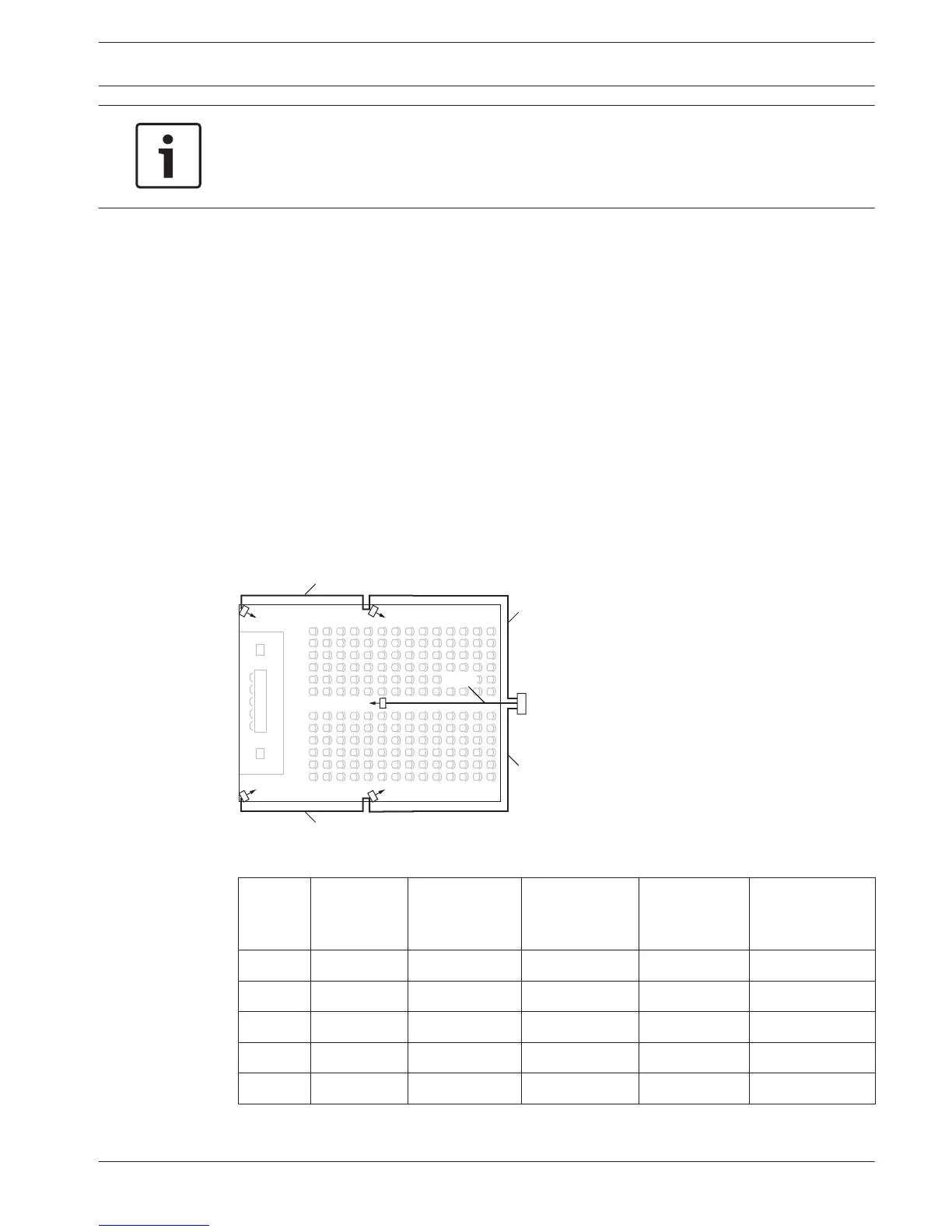
The next figure and table illustrate the calculation of the cable signal delay.
Figure 7.4: System with five radiators and measured cable lengths
Radiator
number
Total cable
length [m]
Cable signal
delay per
meter [ns/m]
Cable signal
delay [ns]
Signal delay
difference
[ns]
Delay switch
position
1 30 5.6 30*5.6 = 168 280-168=112 112/33=3.39=3
2 30+20=50 5.6 50*5.6 = 168 280-208=0 0/33=0
3 20 5.6 20*5.6 = 168 280-112=168 168/33=50.9=5
4 30 5.6 30*5.6 = 168 280-168=112 112/33=3.39=3
5 30+20=50 5.6 50*5.6 = 168 280-280=0 0/33=0
Table 7.1: Calculation of the cable signal delays
Language Distribution System Configuration | en 61
Bosch Security Systems B.V. Operation manual 2013.11 | V1.4 |