Structure, Block Diagrams
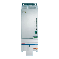
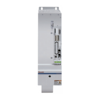
1 power section
2 control section
Fig.6-49: Basic structure of the drive controller
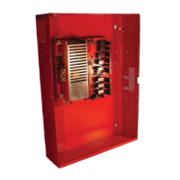
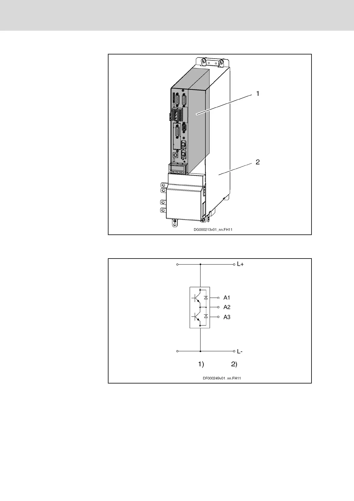
1) inverter stage with output to motor
2) DC bus connection
Fig.6-50: Block diagram
142/369 Bosch Rexroth AG | Electric Drives
and Controls
Rexroth IndraDrive | Project Planning Manual
Power Sections for Inverters - IndraDrive M
 Loading...