occurring current load and minimum required
connection cross section
A see technical data of device used (I
L_cont
, I
L_max
and A
LN
)
occurring voltage load V see technical data of device used (U
LN
)
Fig.8-11: Function, pin assignment, properties
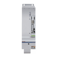
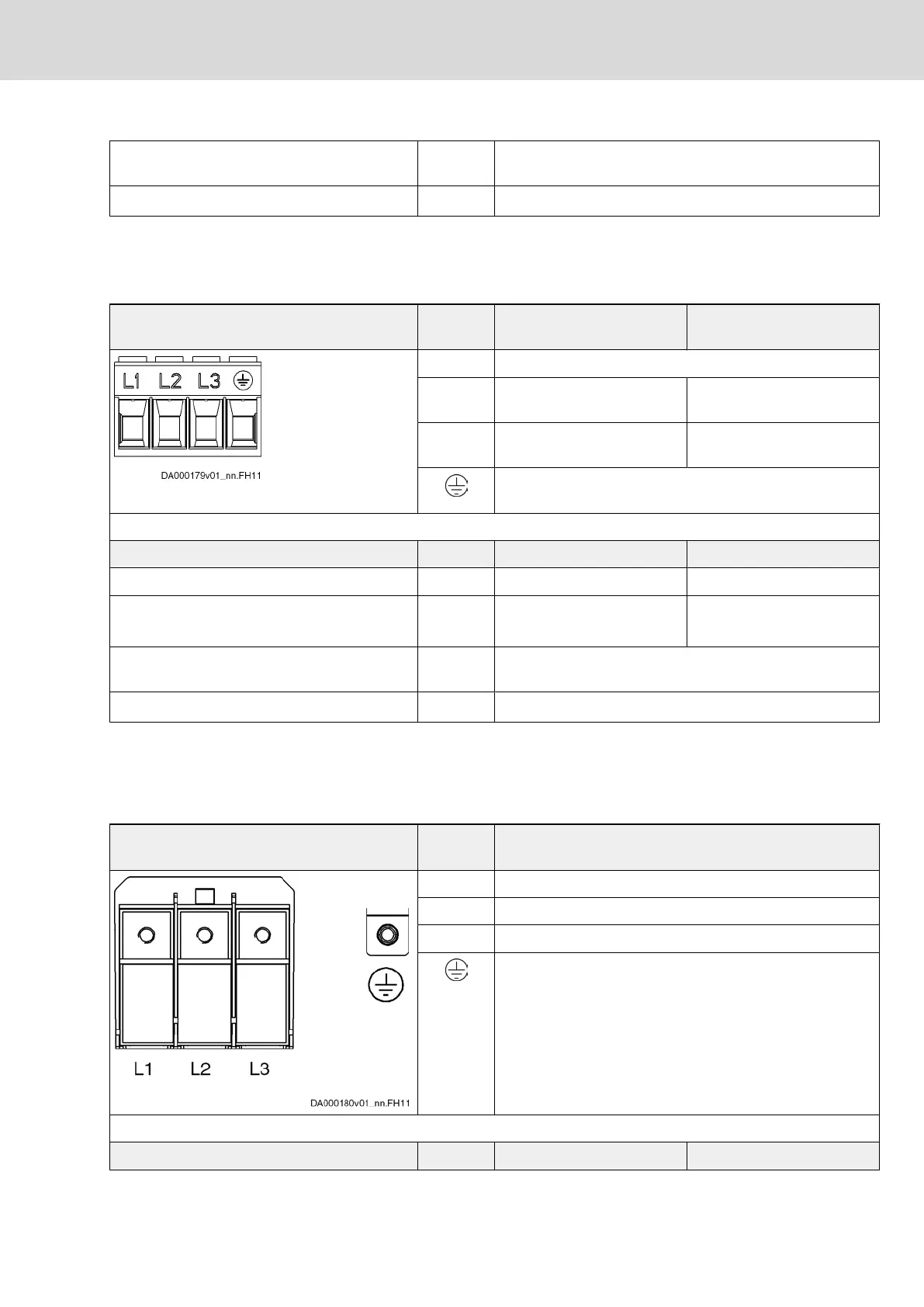
8.5.4 X3, Mains Connection HCS02.1E-W0054, -W0070 and HCS03.1E-
W0070
View Identifica‐
tion
Function 3-phase operation
Function 1-phase operation
1)
L1 connection to supply mains (L1)
L2 connection to supply mains
(L2)
connection to neutral conduc‐
tor supply mains
L3 connection to supply mains
(L3)
n.c.
connection of equipment grounding conductor of drive con‐
troller
Screw connection at connector Unit Min. Max.
tightening torque Nm 1,5 1,7
connection cross section
stranded wire
mm
2
/
AWG
1,5 / 16 16 / 6
occurring current load and minimum required
connection cross section
A see technical data of device used (I
L_cont
, I
L_max
and A
LN
)
occurring voltage load V see technical data of device used (U
LN
)
1) only allowed for HCS02.1E drive controllers
Fig.8-12: Function, pin assignment, properties
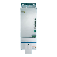
8.5.5 X3, Mains Connection HCS03.1E-W0100…0150 and HMV01.1R-
W0018…0065; HMV01.1E-W0030…0075
View Identifica‐
tion
Function
L1 connection to supply mains (L1)
L2 connection to supply mains (L2)
L3 connection to supply mains (L3)
connection of equipment grounding conductor of drive con‐
troller
Terminal block Unit Min. Max.
Project Planning Manual | Rexroth IndraDrive Electric Drives
and Controls
| Bosch Rexroth AG 251/369
Functions and Electrical Connection Points