8.5.7 X3, Mains Connection HMV01.1E-W0120 and HMV01.1R-W0120
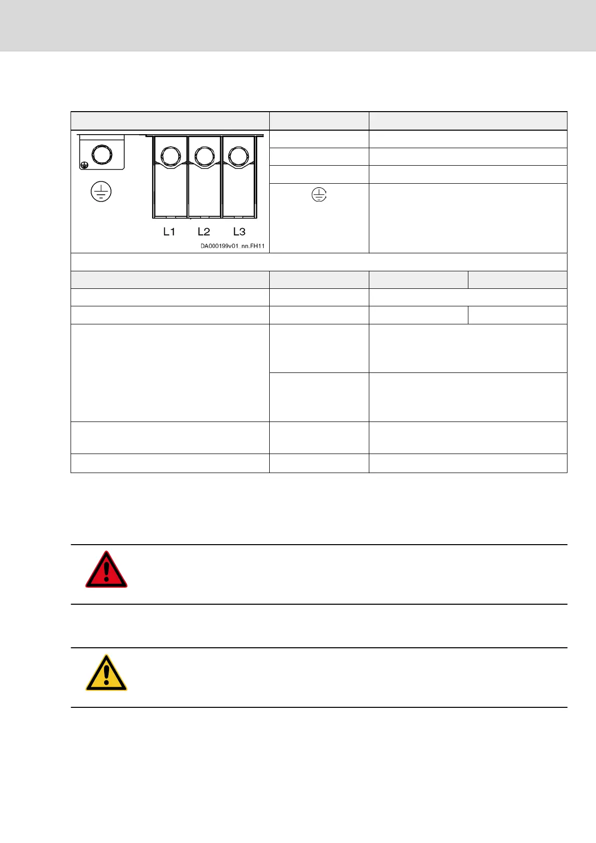
View Identification Function 3-phase operation
L1 connection to supply mains (L1)
L2 connection to supply mains (L2)
L3 connection to supply mains (L3)
connection of equipment grounding conductor of
drive controller
Terminal block Unit Min. Max.
screw thread M10
tightening torque Nm 16 20
connection cables
stranded wire with ring cable lug
mm
2
1×16; 1×25; 1×35; 1×50; 1×70; 1×120
2×16 (with different angles)
2×25; 2×35; 2×50; 2×70; 2×120
AWG 1×6; 1×4; 1×2; 1×1; 1×1/0; 1×2/0; 1×4/0
2×6 (with different angles)
2×4; 2×2; 2×1; 2×1/0; 2×2/0; 2×4/0
occurring current load and minimum required
connection cross section
A see technical data of device used (I
L_cont
, I
L_max
and A
LN
)
occurring voltage load V see technical data of device used (U
LN
)
Fig.8-15: X3, mains connection
8.6 X5, Motor Connection
8.6.1 Important Notes
DANGER
Lethal electric shock caused by live parts with more than 50 V!
Exclusively operate the device with plugged on connector and connected
equipment grounding conductor!
Notes on Installation
The connection cross section data refer to the line cross sections which can be
connected. Dimension the required cross section of the connecting lines ac‐
cording to the occurring current load by the motor which is used.
CAUTION
Damage to the device!
Provide strain relief for the terminal connectors of the device in the control cab‐
inet or use the optionally available connection accessory HAS02.
Project Planning Manual | Rexroth IndraDrive Electric Drives
and Controls
| Bosch Rexroth AG 253/369
Functions and Electrical Connection Points
 Loading...