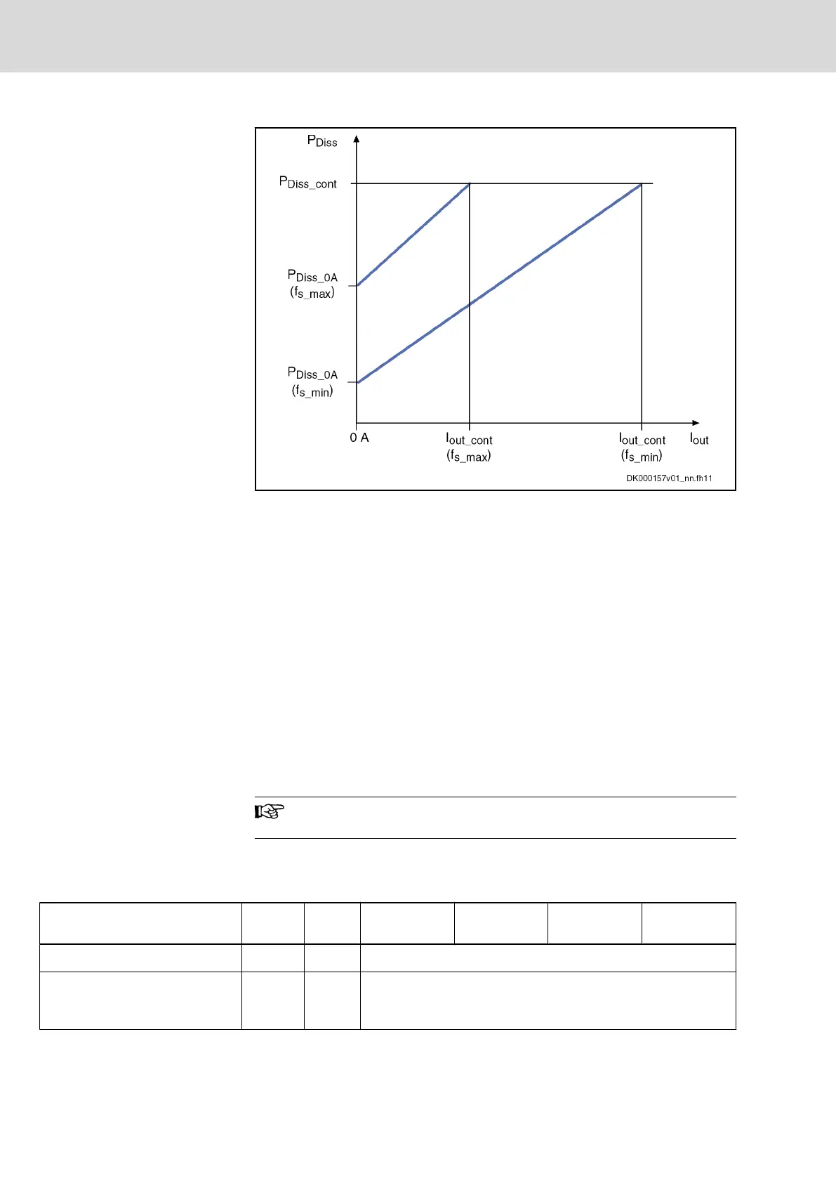
I
out
output current
P
Diss
power dissipation
f
s
switching frequency
Fig.5-22:
Power dissipation vs. output current
Basic Data Power Section HCS02
General Information
This section contains
● data for control voltage supply
● data for mains voltage supply
● data of DC bus
● data of built-in braking resistor and requirements on an external braking
resistor
● data of inverter
● data for cooling and power dissipation
The order of the data tables below follows the energy flow in the
drive controller – from mains connection to motor output.
Control Voltage
Data for control voltage supply
Description Symbol Unit
HCS02.1E-
W0012-_-03
HCS02.1E-
W0028-_-03
HCS02.1E-
W0054-_-03
HCS02.1E-
W0070-_-03
rated control voltage input (UL)
1)
U
N3
V 24 ± 20 %
control voltage when using motor
holding brake with motor cable
length < 50 m
2)
U
N3
V 24 ± 5 %
42/369 Bosch Rexroth AG | Electric Drives
and Controls
Rexroth IndraDrive | Project Planning Manual
Power Sections for Converters - IndraDrive C
 Loading...