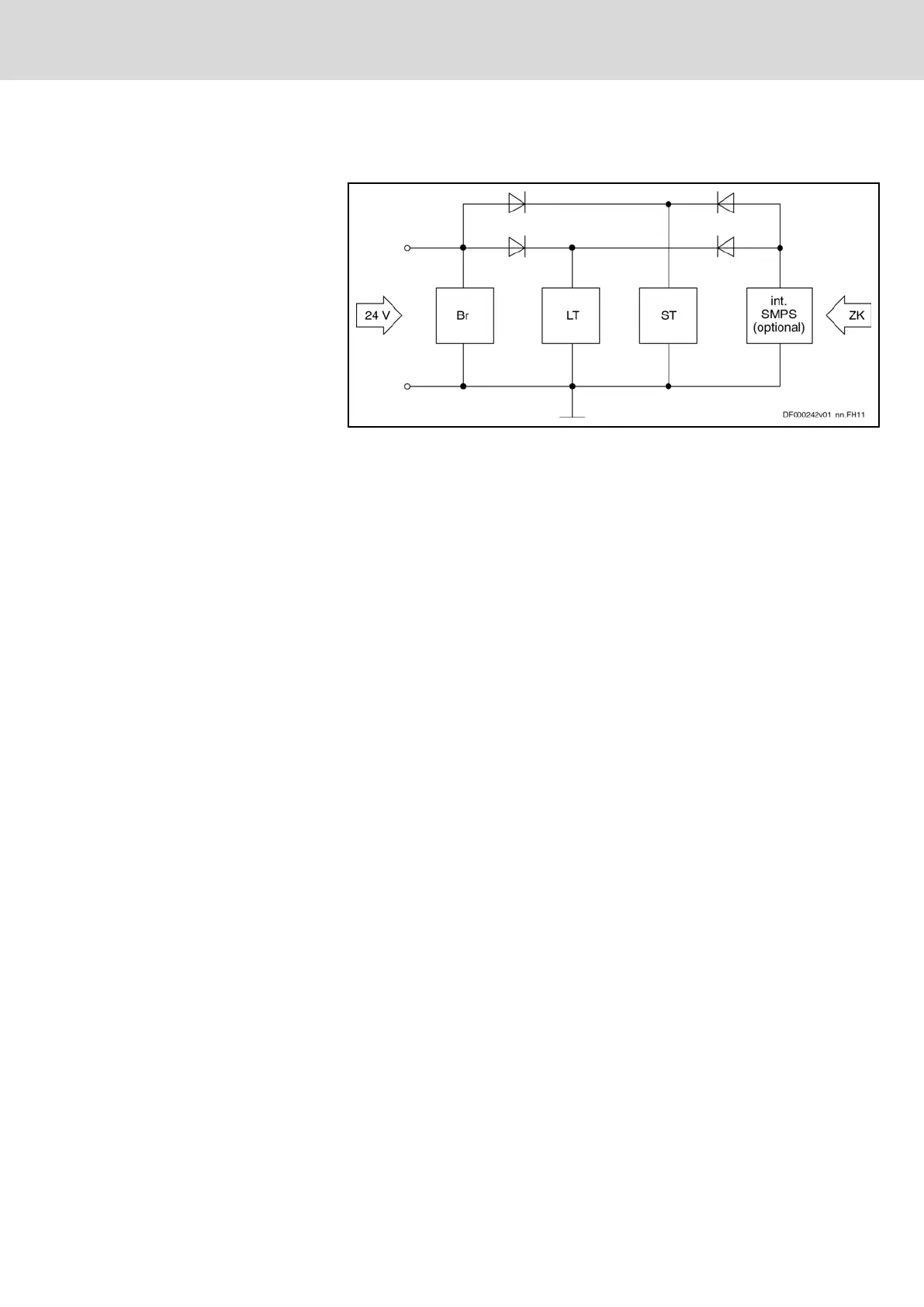
Control Voltage Block Diagram
The control voltage, which is supplied via the connection for 24V supply, takes
effect according to the following block diagram.
BR circuit for brake control
LT power section, e.g. HCS02
ST control section, e.g CSB01
ZK DC bus
int. SMPS internal switching power supply unit, for types HCS0x.1E-Wxxxx-NxxV
Fig.4-13: Block diagram of internal control voltage
Project Planning Manual | Rexroth IndraDrive Electric Drives
and Controls
| Bosch Rexroth AG 25/369
General Specifications of the Devices
 Loading...