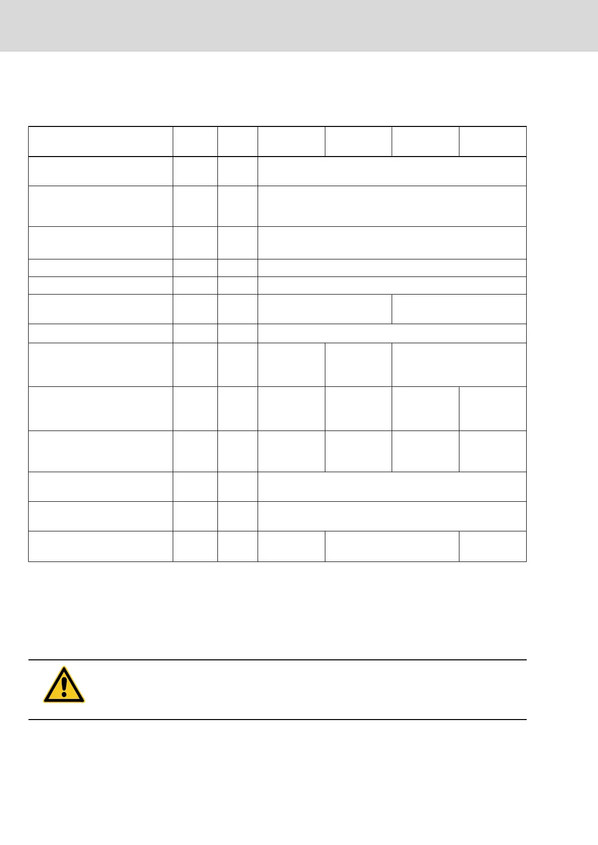
Power Dissipation, Mounting Position, Cooling, Distances
Data for cooling and power dissipation
Description Symbol Unit
HCS02.1E-
W0012-_-03
HCS02.1E-
W0028-_-03
HCS02.1E-
W0054-_-03
HCS02.1E-
W0070-_-03
ambient temperature range during
operation with nominal data
T
a_work
°C 0...40
ambient temperature range during
operation with reduced nominal da‐
ta
T
a_work_red
°C 0...55
derating of P
DC_cont
; P
BD
; I
out_cont
at
T
a_work
< T
a
< T
a_work_red
f
Ta
%/K 2,0
allowed mounting position G1
cooling type forced ventilation
volumetric capacity of forced cool‐
ing
V
m
3
/h
approx. 24 approx. 40
allowed switching frequencies
1)
f
s
kHz 4, 8, 12, 16
power dissipation at I
out_cont
= 0 A;
f
s
= f
s
(min.)
2)
P
Diss_0A_fsmi
n
W 25 35 85
power dissipation at I
out_cont
= 0 A;
f
s
= f
s
(max.)
3)
P
Diss_0A_fsma
x
W 70 110 195 185
power dissipation at continuous
current and continuous DC bus
power respectively (UL)
4)
P
Diss_cont
W 80,00 130,00 270,00 300,00
minimum distance on the top of the
device
5)
d
top
mm 80
minimum distance on the bottom of
the device
6)
d
bot
mm 80
temperature rise with minimum dis‐
tances d
bot
; d
top
; P
BD
ΔT K 12 40 50
1) also depending on firmware and control section; see Parameter De‐
scription "P‑0‑0001, Switching frequency of the power output stage"; see
"P-0-4058, Amplifier type data"
2) 3) plus dissipation of braking resistor (at HMV, HCS) and control section
(at HMx, HCS); find interim values by interpolation to P_Diss_cont
4) HMV, HCS: plus dissipation of braking resistor, control section; KSM:
plus rated power consumption control voltage input
5) 6) see fig. "Air intake and air outlet at drive controller"
Fig.5-20: HCS - Data for cooling and power dissipation
CAUTION
Property damage due to temperatures higher than 105 °C!
Comply with indicated minimum distances!
40/369 Bosch Rexroth AG | Electric Drives
and Controls
Rexroth IndraDrive | Project Planning Manual
Power Sections for Converters - IndraDrive C
 Loading...