11
Bosch Security Systems 10/22 BLCC615R
Solution 6000-IP
Quick Start Guide
+
-
A
B
+
-
A
B
+
-
A
B
-
A
B
+
-
A
B
CONTROL PANEL
CM704-ZONE EXPANDER
KEYPAD
CM720-POWER SUPPLY
CM710-OUTPUT EXPANDER
EARTH
EARTH
EARTH
EARTH
+12V
OUT
LOOP
LAN
TERM
NY
L
A
N
LAN
TERM
NY
LAN
TERM
NY
LAN
TERM
NY
L
A
N
L
A
N
L
A
N
L
A
N
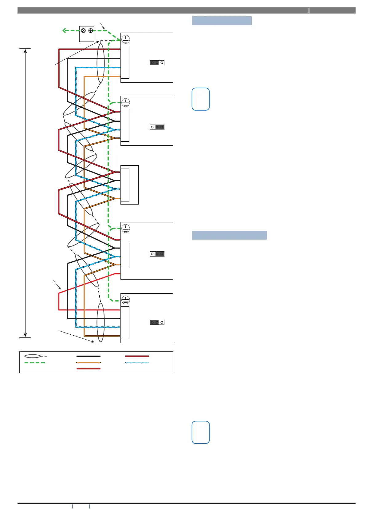
First Device
Last Device
Belden 8723
2 pair twisted
shielded data
cable is
recommended
for this wiring
configuration.
= LAN +
= SHIELD
= EARTH
= LAN A
= LAN -
= LAN B
Shield not
connected
at this end.
C. E. T.
Connect to
main building
earth conductor.
*
Shield only
connected
at one end.
The LOOP
terminal is
not internally
connected.
It can be
used to
terminate
the LAN+
on modules
which have
an on board
power supply.
Positive LAN
voltage is
re-generated
by the CM720
Power Supply.
= RE-GENERATED LAN +
+ - A B
E
A
- A B
B
-
+
A
B
-
+
E
E
E
Fit Shunt
Fit Shunt
1500 metres max
2.5mm
2
Yellow/Green
2.5mm
2
2.5mm
2
2.5mm
2
2.5mm
2
NOTE:
Do NOT connect
plug pack
Earth wires to
any modules
when running
a separate
communication
earth wire.
Figure 19: LAN Connection Using Twisted Pair Cable
The LAN- terminals from all modules must be connected
together for correct operation.
System Earthing
When running a CET communications Earth as per
Figure 19, the communication earth should be connected
to the earth terminal on each module and then connected
back through the CET to the main building earth conductor.
Do NOT connect the plug pack transformers earth wire to
any modules earth terminal.
If a separate Communications Earth wire is
installed, do NOT connect the EARTH wire from
any 3 wire plug pack to any modules EARTH input
terminal.
If a separate communications earth is NOT being used,
then you should connect the earth wire from the 3 wire
plug pack to the panels earth terminal as shown in Figure
19.
When using shielded cable, the shield of each length of
cable should only be connected to a protective earth at one
end. Do no allow the shield to make contact with negative
0 volts, ground or any other wiring within the system.
All earth wiring should be carried out in accordance with
the local wiring regulations in your area.
Terminating the LAN
For reliable operation, the system LAN must be terminated
correctly. The control panel and all LAN modules include a
LAN TERM pin header and shunt which is used to connect
the termination resistor on the module.
When the shunt is installed between the Y pin and the
centre pin, the terminator is fitted and when the shunt is
between the N pin and the centre pin the terminator is not
fitted.
Where all modules are connected to the panel on a single
cable run, (Daisy Chained) the terminators should be
installed on the first and last modules on the LAN.
If the modules are connected to the panel via multiple
cables all running back to the control panel (Star
Configuration) then the terminators should be installed on
the modules at the end of the two longest cable runs.
There are no LAN terminators on keypads. If a keypad is
one of the two furthest devices from the control panel
then a 470 ohm 1/2watt resistor can be fitted at the keypad
between the LAN A and LAN B terminals.
The LAN must be terminated correctly for correct
operation.