5
Bosch Security Systems 10/22 BLCC615R
Solution 6000-IP
Quick Start Guide
About The Panel
Enclosures
The MW720B - Small Enclosure and MW730B - Large
Enclosure have been designed to reduce installation time
and improve aesthetics on larger installations where often
multiple enclosures need to be located in close proximity
to each other.
A number of new features have been incorporated
including a new style tamper bracket which can be easily
installed before or after the enclosure is mounted to the
wall, an anti tamper lid which insures the cabinet tamper
triggers when the lid is removed, easier access for flexible
and rigid conduits, additional 20mm cable entry knockouts
and a new board mounting system using removable spring
clips.
The MW720B and MW730B enclosures include numerous
holes, allowing the PCB mounting clips to be positioned in
the most appropriate location for each installation.
For ease, it is recomended that the PCB mounting
clips are installed from the rear of the enclosure
before mounting it to the wall.
Circuit Board
Component Side
Rear of Cabinet
3mm Philips Head
Machine Screw
Supplied
Support Clip
Press Fit Supplied
Figure 1: PCB and Mounting Clip Installation Diagram
Enclosure Fixing Method
CM720B - Small Enclosure
Use appropriate fasteners capable of handling a minimum
of 6kg to fix the cabinet against a sturdy surface using the
mounting holes provided.
CM730B - Large Cabinet
Use appropriate fasteners capable of handling a minimum
of 12kg to fix the cabinet against a sturdy surface using the
mounting holes provided.
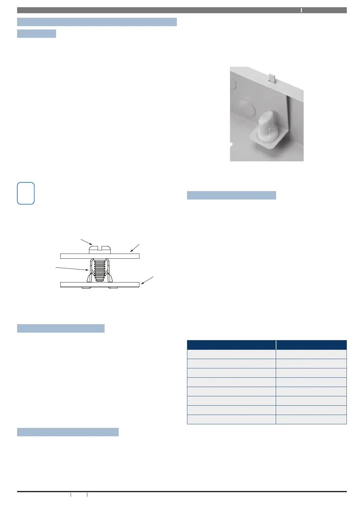
Installing The Tamper Switch
The tamper switch can be located on either the left or right
hand side of the cabinet to suit the installation. Before
installing the bracket, fit the tamper lead to the switch and
then insert it into the bracket.
Once the enclosure has been mounted to the wall, insert
the tamper bracket into the rectangular hole in the top
flange of the enclosure and then slide the base of the
bracket toward the top until the tamper switch locates in
the rear of the enclosure.
Depress the tamper a few times with your finger to ensure
smooth operation.
Figure 2: Tamper Bracket Installation
Enclosure Module Spaces
The MW720B enclosure has space for 2 large modules or
4 small modules while the optional MW730B enclosure
has space for up to 4 large modules or 8 small ones. The
enclosures have been designed so that any combination
of large and small units can be neatly mounted together
on the wall.
Each module is mounted to the enclosure using 4 or more
clip in standoffs. The clips can be inserted from the rear
of the enclosure before mounting it to the wall, or from
the front of the enclosure after it has been mounted. Both
methods should be performed using your finger tips to
prevent damage to the standoff. (Standoffs and screws are
supplied with each module).
All compatible add on modules will mount on these spaces.
See below for list if modules which can be added to the
control panel.
Module Space Occupied
Solution 6000-IP Control Panel 2 Module Spaces
CM704B Zone Expander 1 Module Space
CM705B Universal Expander 2 Module Spaces
CM710B Output Expander 1 Module Space
CM720B LAN Power Supply 1 Module Space
CM760B Real Time Clock 1 Module Space
CM797B LAN Isolator Module 1 Module Space
CM195 RF Receiver Expander 1 Module Space
Table 1: Expansion Options
Use the above table to help determine which size cabinet
you will require for the job.
On some export models, one module space will not be
available as the mains transformer mounts in this location.