31
Bosch Security Systems 10/22 BLCC615R
Solution 6000-IP
Quick Start Guide
Inputs > Zone Properties >
Report Options
MENU 3-1-7
1 Lockout Dialler Y
2 Report Alarm Y
3 Report Troubles Y
4 Report Bypass Y
5 Reserved N
6 Reserved N
7 Report Restores Y
8 Delay Reporting N
Inputs > Zone Properties >
Zone Options
MENU 3-1-8
1 Lockout Siren Y
2 Silent Alarm N
3 Inverted Seal N
4 Bypass Allowed Y
5 Sensor Watch N
6 Armed In Part On Y
7 No EOL Required N
8 Test On Exit Y
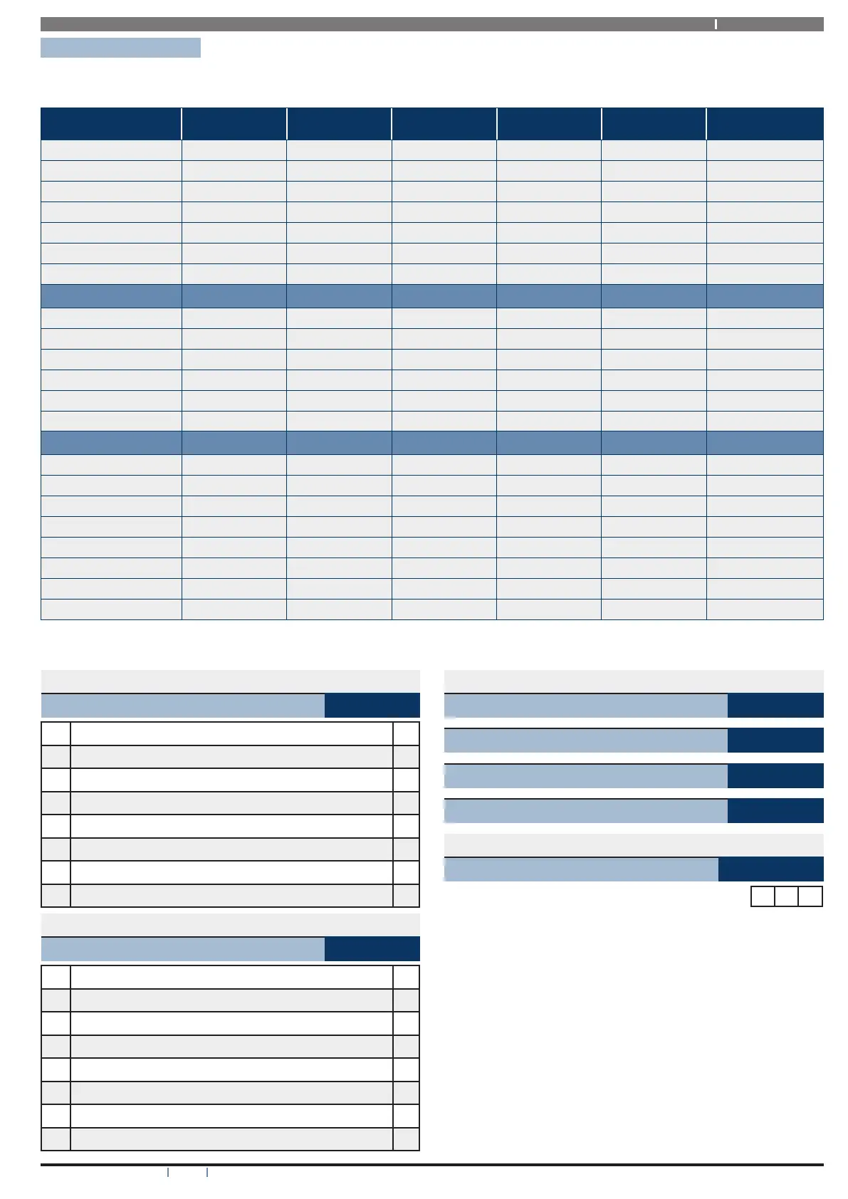
Zone Default Table
The table below list the default values for all zone parameters in the Solution 6000-IP. By default, zones 5 to 16 are set as
Instant zones and zones 17 to 144 are set as Not Used. Zones marked as Not Used do not require EOL resistors to be fitted.
Programming Zone 1 Zone 2 Zone 3 Zone 4 Zones 5 - 16 Zones 17 - 144
Zone Name Zone 1 Zone 2 Zone 3 Zone 4 Zone 5 to 16 Zone 17 to 144
Zone Type 1 = Delay 1 5 = Handover 5 = Handover 5 = Handover 3 = Instant 0 = Not Used
Area Assignment 1 1 1 1 1 1
Pulse Count 0 0 0 0 0 0
Pulse Count Time 120 120 120 120 120 120
Door Assignment 0 0 0 0 0 0
Report Route 2 2 2 2 2 2
Reporting Options
Lockout Dialler Y Y Y Y Y Y
Report Alarm Y Y Y Y Y Y
Report Troubles Y Y Y Y Y Y
Report Bypass Y Y Y Y Y Y
Report Restores Y Y Y Y Y Y
Delay Reporting N N N N N N
Zone Options
Lockout Siren Y Y Y Y Y Y
Silent Alarm N N N N N N
Inverted Seal N N N N N N
Bypass Allowed Y Y Y Y Y Y
Sensor Watch N N N N N N
Armed In Part On Y Y Y Y Y Y
No EOL Required N N N N N N
Test On Exit Y Y Y Y Y Y
Table 17: Zone Defaults
Inputs > RF Zone >
Add RF Device
MENU 3-3-0
Delete RF Device
MENU 3-3-1
Test RF Device
MENU 3-3-2
RF Zone Properties
MENU 3-3-3
Inputs > RF Zone Properties >
Gross Attack
MENU 3-3-3-0
Range 000 - 100 0 7 0