17
Bosch Security Systems 10/22 BLCC615R
Solution 6000-IP
Quick Start Guide
Keypad & Readers Setup
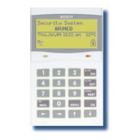
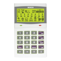
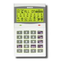
The control panel can have a maximum of 16 keypads and/
or readers connected via the LAN terminals. Each keypad
or reader must be set to a unique address before they will
operate.
Each keypad or reader needs to be assigned to a home area
via MENU 6-1-3. This sets the area the keypad or reader
will display and control by default. Keypads and readers
can be locked to a home area or allowed to roam or move
between areas. At factory default, the home area is factory
default to operate Area 1.
Set each keypad or reader address using “Table 9: DIP
Switch Address Settings” on page 17 and “Table 10:
Rotary Switch Address Settings” on page 17 as a guide.
Only 1 keypad can be assigned to each address. All
keypads are supplied from the factory set to address
1. (OFF-OFF-OFF-OFF).
DIP Switch Address Select
4
Figure 23: Keypad DIP Switch Address Settings
DIP Switch Address Settings
Keypad/Reader N
o
S1 S2 S3 S4
1 Off Off Off Off
2 On Off Off Off
3 Off On Off Off
4 On On Off Off
5 Off Off On Off
6 On Off On Off
7 Off On On Off
8 On On On Off
9 Off Off Off On
10 On Off Off On
11 Off On Off On
12 On On Off On
13 Off Off On On
14 On Off On On
15 Off On On On
16 On On On On
Table 9: DIP Switch Address Settings
Rotary Switch Address Select
Keypads and readers fitted to the system must be assigned
a unique address on the LAN. Some keypads and readers
include a rotary address switch for quick selection.
The following table shows how to set the address setting
for each keypad and reader, as well as the number of
devices the panel can support.
Rotary Switch Address Settings
Address Number Keypad/Reader N
o
1 1
2 2
3 3
4 4
5 5
6 6
7 7
8 8
9 9
10 10
11 11
12 12
13 13
14 14
15 15
16 16
Table 10: Rotary Switch Address Settings
Figure 24: Rotary Swich Address Settings
Programming Overview
The control panel incorporates a menu text driven interface.
This interface is very similar to that found on many mobile
phones. Once programming mode is entered you will see a
number of menu options in the display and these may vary
depending in the user authority level.
Entering Programming Mode
To enter installer program mode enter, PIN + [MENU].
The default Installer PIN is 1234.
The Red and Green LED indicators on the keypad will flash
to confirm Installer programming mode is active.

 Loading...


