Solution 6000-IP
14
Bosch Security Systems 10/22 BLCC615R
Quick Start Guide
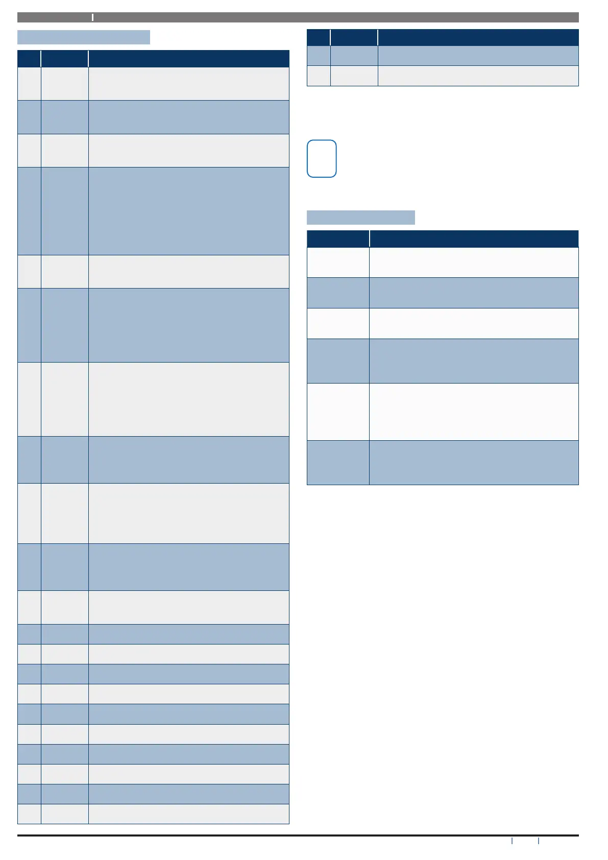
Terminal Descriptions
Nº Name Description
1 Earth
Earth wire from this terminal is connected
to the Mains earth.
2
3
~ (AC)
~ (AC)
Connection of the AC plug pack
transformer
4
5
BAT (-)
BAT (+)
Negative and positive connections to the
stand-by battery. 12 VDC / 7AH
6
7
8
9
10
11
+12 V
+12 V
+12 V
GND
GND
GND
These terminals are used to power
detectors and LAN devices up to 750 mA.
12
13
LAN +
LAN -
These terminals are used to power LAN
devices up to 750 mA.
14 LAN A
Connect the LAN A data terminal of any
LAN device (eg. Keypads, expansion
boards) to this terminal. The control
panel supports up to 300 m of 24/0.20
(18 AWG) wire on these terminals.
15 LAN B
Connect the LAN B data terminal of any
LAN device (eg. Keypads, expansion
boards) to this terminal. The control
panel supports up to 300 m of 24/0.20
(18 AWG) wire on these terminals.
16 COMM+
Alarm power capable of providing a
maximum of 2.5 Amp (+). This terminal
is PTC Fuse protected.
17
18
19
20
OUT 1
OUT 2
OUT 3
OUT 4
Programmable output, capable of
providing a maximum of 500 mA (-). This
terminal is PTC Fuse protected.
21
22
23
N/C
COM
N/O
2 A @ 24 VDC Relay Output -
Form C contact
24 INPUT
Programmable Input for RF Receivers,
Keyswitch and other devices.
25 ZN 1 Zone 1 and 9 sensor loop input (+).
26 GND Common (-) for Zone 1 and 2 sensor loop.
27 ZN 2 Zone 2 and 10 sensor loop input (+).
28 ZN 3 Zone 3 and 11 sensor loop input (+).
29 GND Common (-) for Zone 3 and 4 sensor loop.
30 ZN 4 Zone 4 and 12 sensor loop input (+).
31 ZN 5 Zone 5 and 13 sensor loop input (+).
32 GND Common (-) for Zone 5 and 6 sensor loop.
33 ZN 6 Zone 6 and 14 sensor loop input (+).
34 ZN 7 Zone 7 and 15 sensor loop input (+).
Nº Name Description
35 GND Common (-) for Zone 7 and 8 sensor loop.
36 ZN 8 Zone 8 and 16 sensor loop input (+).
Table 4: Terminal Block Descriptions
The maximum combined continuous current draw
from the +12V, LAN + and COMM+ terminals must
not exceed 1 Amp
Board Connectors
Connector Description
Service
This socket allow you to connect a service
Keypad to the panel during installation.
Tamper
This socket is used to connect the panel
enclosure tamper switch.
Default
This push button is used to reset the con-
trol panel back to factory default.
Serial
This socket is used to connect serial devic-
es to the control system like the direct link
programming module.
Relay
The relay select PIN’s allow you to eas-
ily program the relay common contact to
switch either +12v or GND by fitting a plug
on link.
Expansion
Port
This port is used to connect additional
modules to the control panel (eg. TCP/IP
Interface Module etc)
Table 5: Board Connector Descriptions