9
Bosch Security Systems 10/22 BLCC615R
Solution 6000-IP
Quick Start Guide
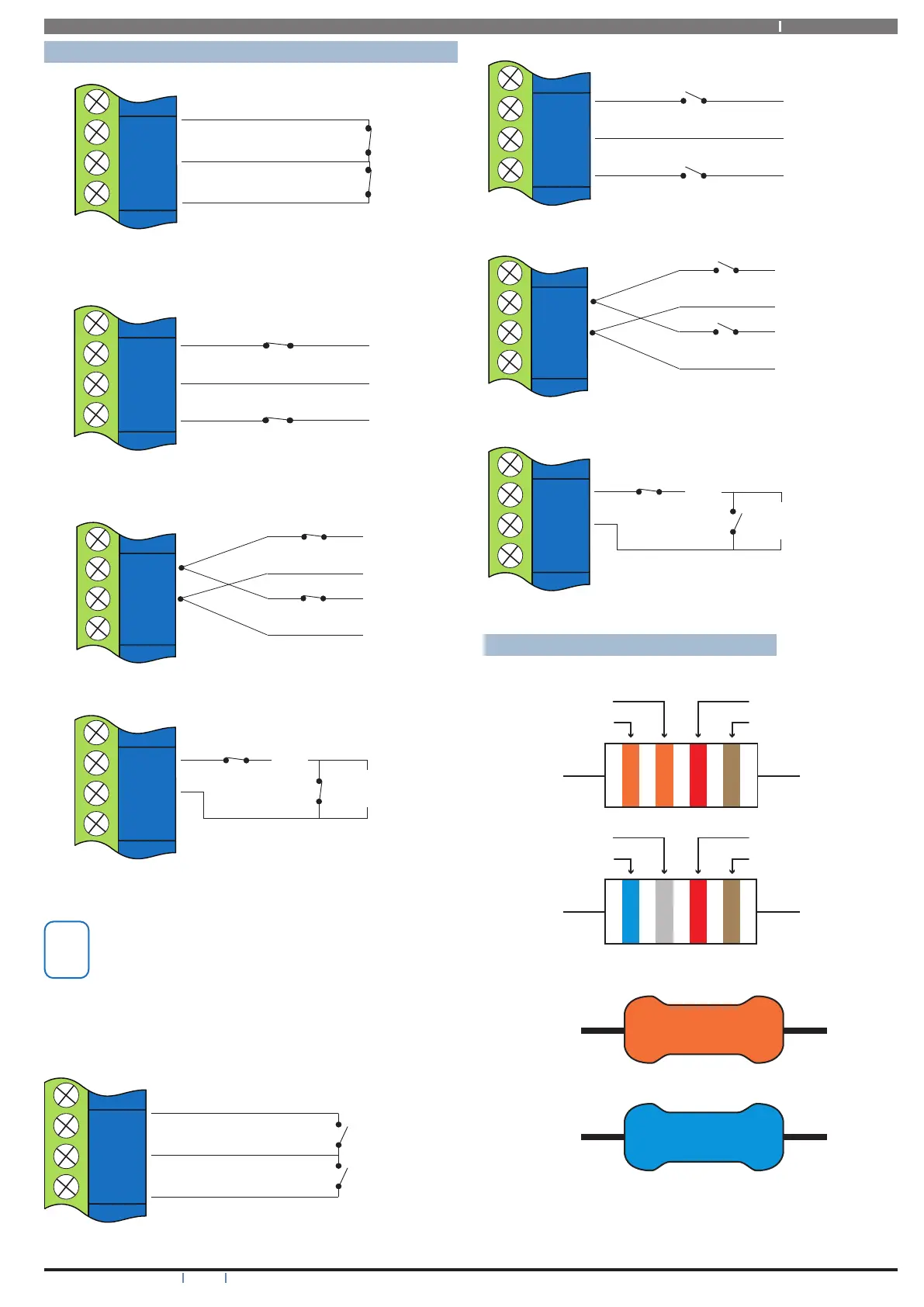
Wiring Diagrams
ZONE 2
N/C
N/C
ZONE 1
ZN 1
GND
ZN 2
Figure 9: N/C No EOL Zone
ZONE 2
ZONE 1
N/C
N/C
ALARM
ALARM
ZN 1
GND
ZN 2
Figure 10: N/C Single EOL Zone
(6K8 EOL)
(3K3 EOL)
N/C
N/C
ALARM
ALARM
ZN 1
GND
ZN 2
ZONE 1
ZONE 9
Figure 11: N/C Split EOL Zone
1
2
TAMPER
(6K8 EOL)
TAMPER
(3K3 EOL)
N/C
N/C
ZN 1
GND
ZN 2
ALARM
ZONE 1
Figure 12: N/C Zone With Tamper
The above diagrams display zone configurations
using Normally-Closed Alarm contacts and
Normally-Open Alarm Contacts. When using
Normally-Open Alarm Contacts you must select
Inverted Seal for each zone in MENU 3-1-8.
A shorted loop is a tamper condition for all EOL
zone configurations.
2
ZONE 2
N/O
N/O
ZONE 1
ZN 1
GND
ZN 2
Figure 13: N/O No EOL Zone
ZONE 2
ZONE 1
N/O
N/O
ALARM
ALARM
ZN 1
GND
ZN 2
Figure 14: N/O Single EOL Zone
(6K8 EOL)
(3K3 EOL)
N/O
N/O
ALARM
ALARM
ZN 1
GND
ZN 2
ZONE 9
ZONE 1
Figure 15: N/O Split EOL Zone
TAMPER
(6K8 EOL)
TAMPER
(3K3 EOL)
N/C
N/O
ZN 1
GND
ZN 2
ALARM
ZONE 1
Figure 16: N/O Zone With Tamper
EOL Resistor Colours and Values
Use either the 4 colour, or solid colour resistors supplied.
Blue
Red
Orange
Grey
3K3
6K8
Brow n (+/- 1%)
Brow n (+/- 1%)
Figure 17: EOL Resistor Colour Chart