6
-
31
42hW-201601
CHAPTER 6 HYDRAULIC SYSTEM
6
3015R(h)/3515R(h)/4015R(h)/F36R(h)/F42R(h) TRACTOR
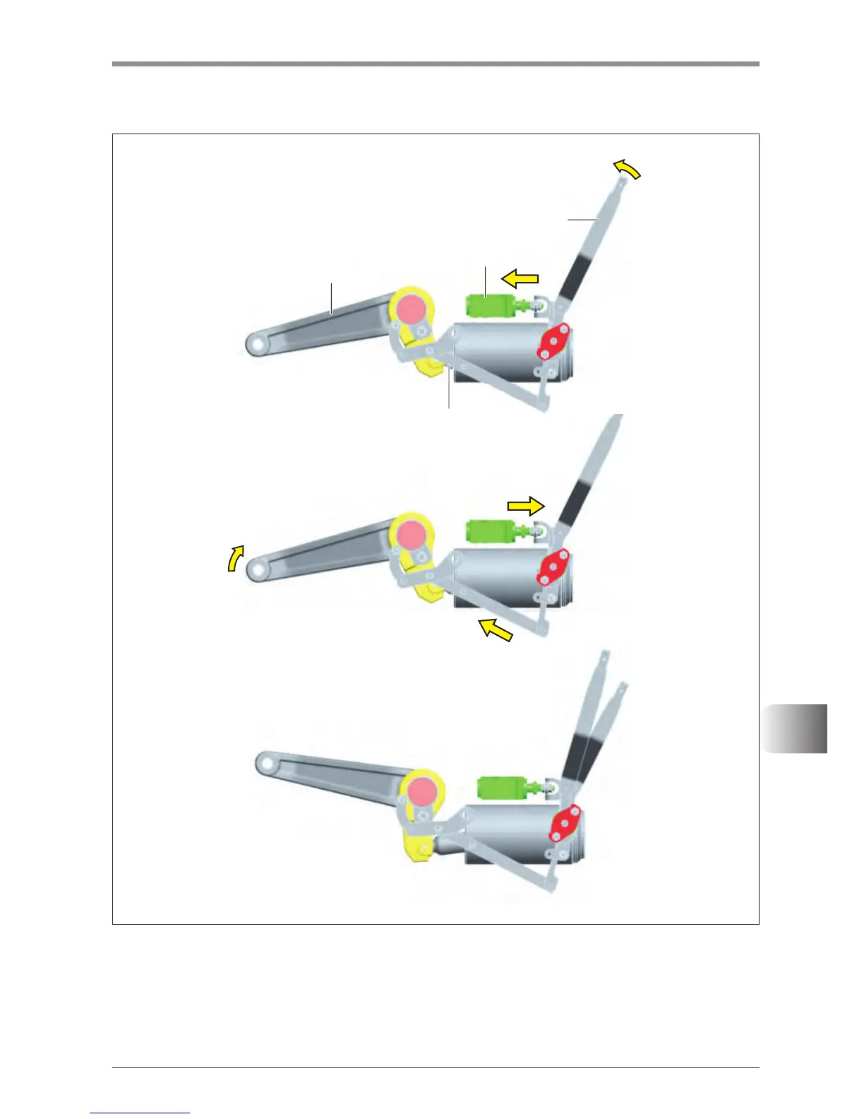
LIFTING
▶
When the control lever is set to the Lifting position, the control valve spool behind the hydraulic cylinder case
is pressed and oil is owed intothe cylinder. Then, the piston lifts the lift arm. However, as the feedback
rod installed to the lift arm is operated to provide a lifting signal in this state, the spool of the control valve is
returned to the neutral position even with the control lever still in the lifting position. Therefore, the spool is
returned to the neutral position during the lowering operation as well.
(1) Lift arm (2) Control lever (3) Control valve (4) Feedback rod