60 1019572 REV. 03
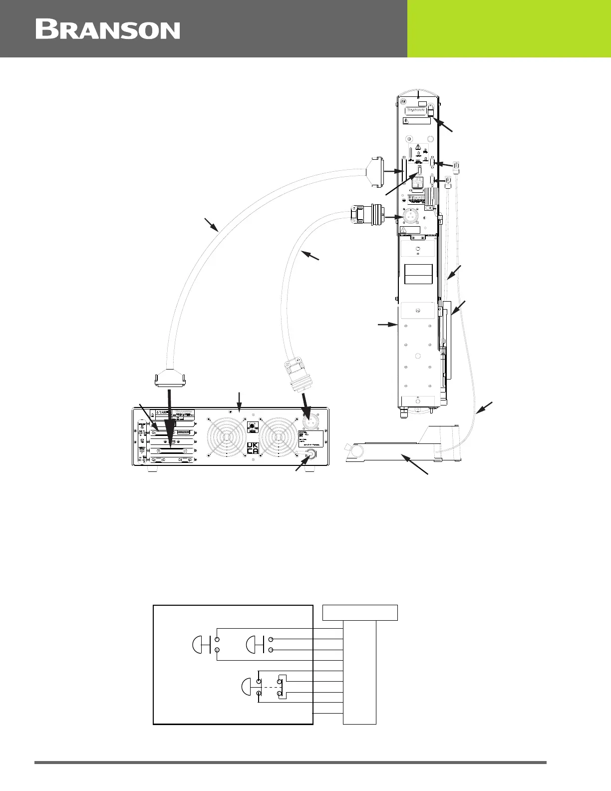
Figure 4.16 Electrical Connections from Power Supply to a 2000X-series Actuator
4.5.8 Start Switch Connection (Automation)
A Branson actuator requires two start switches and emergency stop connection. Stands on
a base include this connection (factory installed and connected from the base) while the
stand on a hub and actuator (alone) applications require the user make their own start
switch/E-stop connections, as follows:
Figure 4.17 Start Switch Connection Codes
IMPORTANT
FOR MOUNTING OF
ACTUATOR USE
M10 X 1.5 FASTENERS
DO NOT ALLOW BOLT
TO PENETRATE
ACTUATOR MORE
THAN 10MM (.4")
GROUND UNIT
BEFORE OPERATING
DISCONNECT
AIR AND POWER
BEFORE SERVICING
IMPORTANT
AIR SUPPLY MUST BE FREE OF OIL AND WATER
MAX. PRESSURE 100PSI/690 kPA/6.89 bar
AIR INLET
CAUTION
100 PSI MAX.
Air Inlet*
Linear Encoder**
Linear Encoder
Cable**
Line Cord
Base, shown rotated 90° CCW
Start Switch
Cable
Actuator
Interface Cable
J931s
RF Cable
Alarm I/O,
Optional
Power Supply
rear view
Actuator
MPS/GDS
*ae/aed actuator air input shown
**aed only
P69
EMER
STOP
START SWITCHES
PB1PB2
1
2
3
4
5
6
7
PB2RTN
9
8
Color Codes
PB1RTN
PB1SRC
PB2SRC
ESTOPSRC
ESTOPSRC
ESTOPRTN
ESTOPRTN
N/C
Blue
Black
White
Orange
Purple
Yellow
Red
Green
Brown