54 1019572 REV. 03
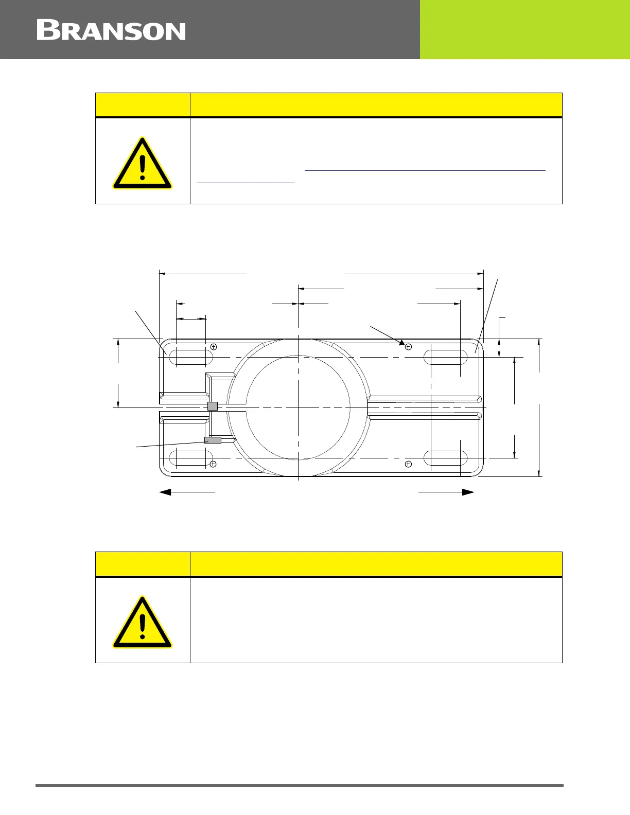
Figure 4.12 Mounting Bolt Pattern for the Hub (for Stand on Hub)
1. Locate the hub in the desired location. Ensure no overhead or side obstructions will interfere with
normal operation or use of the system.
2. Carefully lift the actuator and column assembly, and mount the column in the hub. Align the flat
face of the spring swivel with the top-front of the actuator. Tighten the two bolts on the hub.
3. Connect factory air to the air hose on the stand (1/4 NPT male fitting on the hose). A quick-
disconnect fitting is suggested. Use a lockout device on the air line if required.
4. Verify the base/start switch control cable is properly connected to the back of actuator.
5. Verify the linear encoder connector is properly connected to the back of the actuator.
CAUTION
The hub must be installed with its front in the same direction as the
front of the actuator. The column bolts of the hub are found on the
rear of the hub. See Figure 4.12
Mounting Bolt Pattern for the Hub
(for Stand on Hub) for mounting details.
CAUTION
Mount the hub to your work surface using four bolts, 3/8-inch or M10
shank size, with flat washers against its metal casting (customer
provided hardware).
10.50 in / 267 mm
6.00 in / 152 mm
5.25 in / 133 mm
0.94 in / 24 mm
(four places)
3.25 in /
83 mm
4.44 in /
113 mm
3.94 in / 100mm
2.22 in /
56 mm
0.59 in /
11 mm
3/8 inch or
M10 bolts
Front of Hub
Column
Bolts
(4 places)
Jack Screws(4)
Front of Hub
Rear of Hub