58 1019572 REV. 03
3. Lift the actuator assembly into position on your mount, and secure using the metric bolts
provided.
4.5.4 Mount the Power Supply
The power supply is designed to be placed on a workbench (rubber feet on bottom) within
cable-length limits of the actuator, or it may be rack-mounted in a standard 19-inch Rack
(using an optional rack mount handle kit). It has two rear-mounted fans which draw
cooling air from rear to front, which must be free from obstruction. Do not place the power
supply on the floor or in other locations that will allow dust, dirt or contaminants to be
drawn into the power supply.
The controls on the front of the power supply must be accessible and readable for setup
changes.
All electrical connections are made to the rear of the power supply, which should be
positioned in your workspace with adequate clearance (approximately 4 inches or more on
either side, and 6 inches to the rear) for cable access and ventilation. Do not place
anything on top of the power supply case.
In the event the system is to be installed in a high dust environment, the use of a fan filter
kit (101-063-614) is required.
See Figure 4.6
for a dimensional drawing of the 2000X Power Supply.
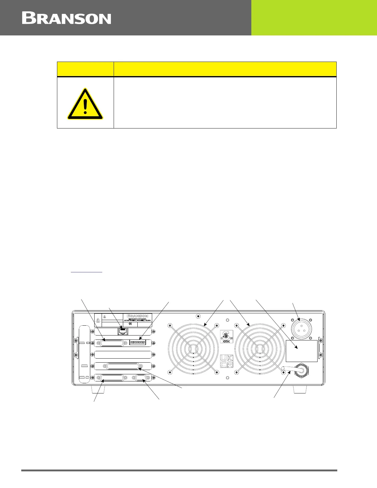
Figure 4.15 Connections on Rear of Power Supply
The cable lengths are limited based on the operating frequency of the welding system.
Performance and results can suffer if the RF cable is crushed, pinched, damaged or
modified. Contact your Branson Representative if you have special cable requirements. In
some cases, remote operation from a User I/O or a Host Computer can be used to solve a
distance limitation.
CAUTION
In the event you must use bolts of a different length, ensure that the
bolts extend more than 0.25 inch (6 mm) into the threads in the
actuator housing, but less than 0.40 inch (10 mm).
Fans
RF Connector
(ultrasonic energy out)
Power Cord
Parallel Printer Connector
Actuator Interface Connector
Model Data Tag
User I/O Connector
Serial Port (RS-232) Connector for Host Computer
US ER I/O
J3 SW1
ACTU ATOR
SIGNAL S
J7
HOST
TERM
J9 J8
MODEL
PRINT ER
THIS EQU IPMENT COM PLIES WI TH
F.C.C. REGU L AT IONS PAR T 18
EDP NO.
WARNING
THI S EQUI PMENT C OMPLIES WITH
F.C.C.REGUL ATIONS PART 18
GROUP 2 C LASS A ISM
MAX POWER
Serial No.
Year & Month of Manufacture
INPUT
DIP Switch for User I/O
Ethernet Connector (Optional)