1019572 REV. 03 63
DIP switch SW1 for the user I/O is located next to the J3 on the back of the 2000X-series
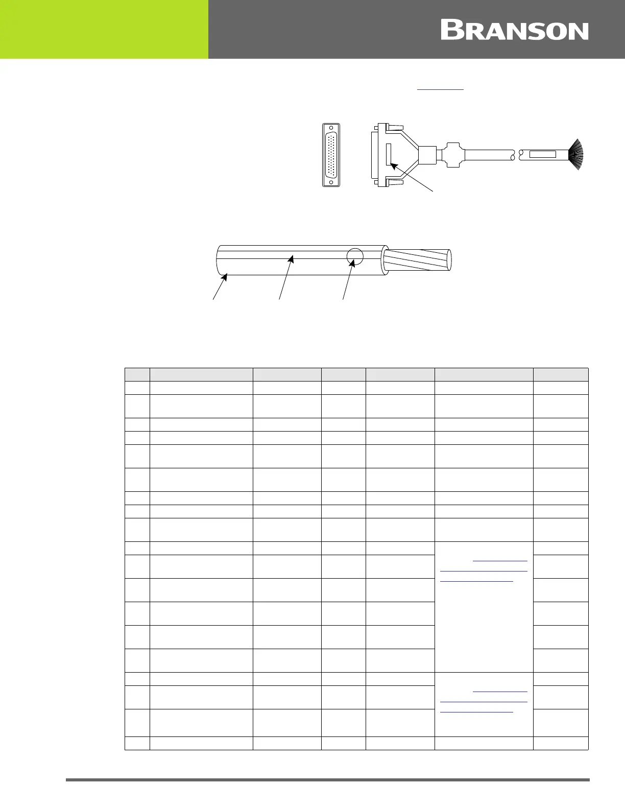
power supply. User I/O interface cable pinout is listed in Table 4.7
.
Figure 4.18 User I/O Cable Identification and Wire Color Diagram
Table 4.7 User I/O Cable Pin Assignments
Pin Signal Name Signal Type Direction Signal Range Definition Colors
7 ACT_CLEAR 0V True Output 0/24V, 100mA Actuator clear signal Red/Wht
24 AMPLITUDE_OUT Analog Output 0V to 10V Amplitude signal from
PS
Red/Blk/
Grn
2 CYCLE_ABORT 24V True Input 0/24V, 100mA Red/Blk
3 EXT_RESET 24V True Input 0/24V, 100mA System Reset Grn/Blk
18 EXT_SEEK+ 24V True Input 0/24V, 100mA Red/Blk/
Wht
38 FREQ_OUT Analog Output -10V to +10V Frequency Signal from
PS
Blk/Wht/Blu
6 G_ALARM 0V True Output 0/24V, 100mA Blk/Wht
14 GEN_ALARM_RELAY_1 Relay Contact Output 40V, 0.25A Contact Closure Red/Grn
29 GEN_ALARM_RELAY_2 Relay Contact Output 40V, 0.25A Contact Closure Wht/Red/
Orn
1 J3_1_INPUT 24V True Input 0/24V, 100mA User definable inputs.
Refer to Table 4.8
User
I/O Input and Output
Function Selection to
view available
selections.
Wht/Blk
17 J3_17_INPUT 24V True Input 0/24V, 100mA Wht/Blk/
Red
19 J3_19_INPUT 24V True Input 0/24V, 100mA Grn/Blk/
Wht
31 J3_31_INPUT 24V True Input 0/24V, 100mA Wht/Red/
Blu
32 J3_32_INPUT 24V True Input 0/24V, 100mA Blk/Wht/
Grn
33 J3_33_INPUT 24V True Input 0/24V, 100mA Wht/Blk/
Grn
8 J3_8_OUTPUT 24V True Output 0/24V, 100mA User definable outputs.
Refer to Table 4.8
User
I/O Input and Output
Function Selection to
view available
selections.
Grn/Wht
22 J3_22_OUTPUT 24V True Output 0/24V, 100mA Blk/Red/
Grn
36 J3_36_OUTPUT 24V True Output 0/24V, 100mA Orn/Red
Grn
9 MEM Analog Output -10V to +10V Memory Signal from PS Blu/Wht
User I/O Cable
Stripped and tinned one end,
HD-44 male connector other end
(cable length as ordered)
Part number
Wire Color Diagram
Two Colors = Insulator/Stripe
Three Colors = Insulator/Stripe/Dot
Insulation Stripe Dot