64 1019572 REV. 03
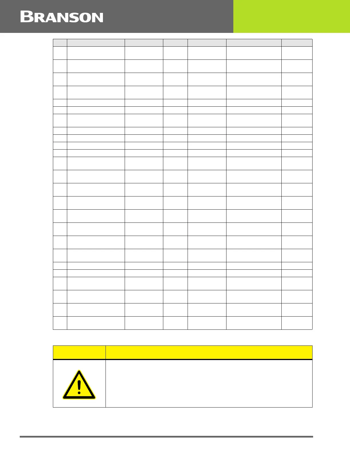
11 MEM_CLEAR Open Collector Output 24V, 25mA max Memory Clear signal
send to PS
Wht/Red
40 MEMORY_STORE Open Collector Output 24V, 25mA max Memory store from PS Red/Wht/
Blu
34 PB_RELEASE 0V True Output 0/24V, 100mA Red/Wht/
Grn
37 PWR Analog Output 0V to 10V Power Signal from PS Blu/Red/
Grn
21 READY 0V True Output 0/24V, 100mA Blu/Blk/Wht
5 REJECT 0V True Output 0/24V, 100mA Blu/Blk
43 READY_ RELAY_1 Relay Contact Output 40V, 0.25A Contact Closure Blu/Orn/
Red
15 READY_RELAY_2 Relay Contact Output 40V, 0.25A Contact Closure Orn/Grn
26 RUN Open Collector Output 24V, 25mA max Run signal send to PS Orn/Blk/Grn
39 SEEK Open Collector Output 24V, 25mA max Seek Signal send to PS Wht/Blk/Blu
4 SOL_VALVE_SRC 24V Output 0/24V, 125mA SV1 Source Orn/Blk
16 SOL_VALVE_RTN 24V Return Input 0V SV1 Return Blk/Wht/
Red
20 SUSPECT_PART 0V True Output 0/24V, 100mA Orn/Blk/
Wht
10 USER_AMP_IN Analog Input -10V to +10V User Amplitude control
signal
Blk/Red
25 USER_FREQ_OFFSET Analog Input -10V to +10V User Freq. offset control
signal
Grn/Blk/Orn
35 WELD_ON 0V True Output 0/24V, 100mA Start of sonics and trig-
ger
Grn/Wht/
Blu
30 WELD_ON_RELAY_1 Relay Contact Output 40V, 0.25A Contact Closure Orn/Wht/
Blu
44 WELD_ON_RELAY_2 Relay Contact Output 40V, 0.25A Contact Closure Blk/Orn/
Red
23 +10V_REF Analog Output 10.0V 10VDC ref. voltage from
PS
Wht/Red/
Grn
12 24V_RTN 24V Ground Input 0V 24V Return Orn/Red
13 24V_SRC 24V Source Output 24V, 1.25A max 24V Source Blu/Red
27 24V_RTN 24V Ground Input 0V 24V Return Blu/Wht/
Orn
28 24V_SRC 24V Source Output 24V, 1.25A max 24V Source Blk/Wht/
Orn
41 24V_RTN 24V Ground Input 0V 24V Return Grn/Orn/
Red
42 24V_SRC 24V Source Output 24V, 1.25A max 24V Source Orn/Red/
Blu
CAUTION
Ensure all unused wires are properly isolated. Failure to do so may
result in Power Supply or system failure.
Pin Signal Name Signal Type Direction Signal Range Definition Colors