56 1019572 REV. 03
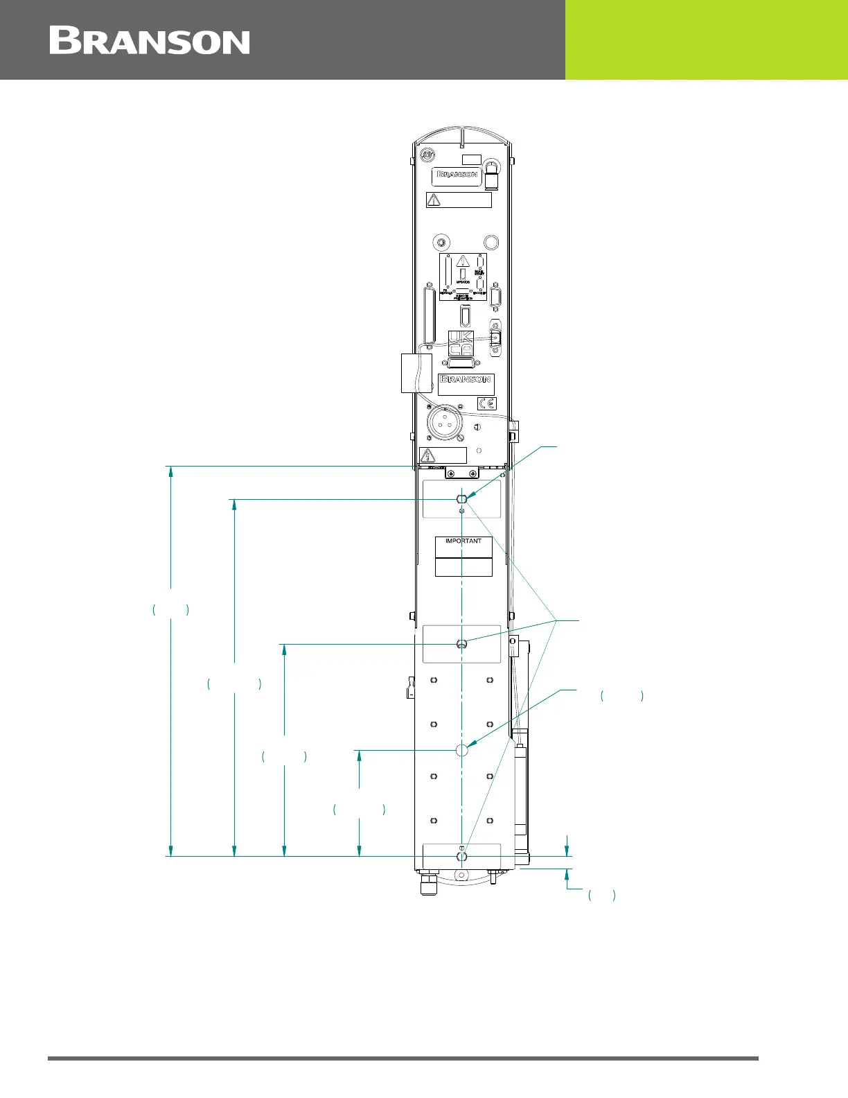
Figure 4.13 Rear view of Actuator, showing Mounting Surface, Bolt and Guide Pin locations
Rear view of ae/aed actuator is shown. Although other actuators will vary in height, referenced dimensions will
be the same for all models.
**These three mounting surfaces are flat within 0.004 in. (0.1mm) TIR, in a tolerance zone of 16 x 3.5 in.
(410 x 90 mm). The surface to which the actuator is mounted must also have the same flatness tolerance.
AIR INLET
CAUTION
AIR SUPPLY MUST BE FREE OF OIL AND WATER
MAX. PRESSURE 100 PSI/690 kPa/6.89 bar
,03257$17
GROUND UNIT
BEFORE OPERAT ING
DISCONNECT
AIR AND POWER
BEFORE SERVICING
FOR MOUNTING OF
ACTUATOR USE
M10 X 1.5 FASTENERS
DO NOT ALLOW BOLT
TO PENETRATE
ACTUATOR MORE
THAN 10MM (.4")
14*."9
.95)%4
..%&&1
1-$4
%08&-1*/
%5$16218/75$621,&6&25325$7,21
3DUN5LGJH5G%URRNILHOG&7
0$'(,10(;,&2
*5283&/$66$
,60
0DFKLQHGPRXQWLQJ
VXUIDFHVSODFHV