CHAPTER 4 DISASSEMBLY AND RE-ASSEMBLY
4-59
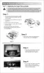
3.22 Toner Sensor PCB Unit (Light Reception)
NOTE:
Be sure to disconnect the toner sensor (light reception) connector on the engine PCB before
removing the toner sensor PCB ASSY (light reception).
(1) Remove the harness from the hooks on the fan duct.
(2) Release the three hooks, and then lift up slightly and slide the fan duct to remove it.
(3) Remove the cup S tite 3x6 screw to remove the toner sensor PCB unit.
Fig. 4-90
3.23 Toner LED PCB Unit (Light Emission)
NOTE:
Be sure to disconnect the toner LED (light emission) connector on the engine PCB before
removing the toner sensor PCB ASSY (light emission).
Release the two hooks from the LED holder and remove the toner LED PCB unit (light
emission) by pulling upward.
(hook)
Toner Sensor PCB Unit
Main frame R
(hook)
Toner Sensor PCB Unit
Fan duct
(hook)
Toner LED PCB unit
Main frame
Screw, cup S tite 3x6
(hooks)
 Loading...