CHAPTER 4 DISASSEMBLY AND RE-ASSEMBLY
4-29
!
CAUTION:
• Never touch the reflect mirror and lens inside the laser unit. If there is any dirt or dust on
the mirror or lens, blow it off using an air gun.
• Never touch the scanner window on the printer body. If there is any dirt or dust on the
window, blow it off using an air gun. If cleaning the underside of the scanner window, wipe
off dirt or dust with soft clean paper. Refer to subsection 3.3 Cleaning the Scanner
Window in CHAPTER 5.
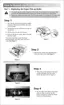
Fig. 4-48
3.12 Fixing Unit
(1) Place the main frame on its base so that the rear side is facing you.
(2) Disconnect the two connectors of the heater harness and release the harness from the
hooks on the right side of the fixing unit.
(3) Remove the shoulder screw and the cup S M3x8 Taptite screw securing the fixing unit.
(4) Remove the fixing unit from the main frame.
Fig. 4-49
Printer body
Scanner window
Fixing unit
Main frame
Shoulder screw
Heater harness
Taptite, cup S M 3x8
Laser unit
Reflect mirror
Lens
Thermistor connector
 Loading...