Home
Brother
Printer
HL-1870N
Service Manual
Page 64
Brother HL-1870N - Page 64
302 pages
Manual
To Next Page
To Next Page
To Previous Page
To Previous Page
Loading...
HL-1850/1870N SE
RVICE
MANUAL
2-35
BOTTOM MARGIN
=####
Set the bottom margin a distance fr
om
the top edge of the paper:
0, 0.33, 0.5, 1.0, 1.5 or 2.0
Factory
setting=0.33
LINES
=####
Set the number of lines per page fr
om 5
to 128 lines.
63
65
Table of Contents
Main Page
Default Chapter
1
Service Manual
1
Table of Contents
4
Regulation
10
Safety Information
12
Chapter 1 General
16
Features
16
Overview
18
Specifications
19
Printing
19
Functions
20
Electrical and Mechanical
21
Network
22
Paper
23
Feedable Paper
23
Paper Cassette Capacity
25
Print Delivery
25
Pcl5E/Epson/Ibm Emulation
26
PCL6/BR-Script3 Emulation
29
Chapter 2 Installation and Basic Operation
30
Conditions Required for Installation
30
Power Supply
30
Environment
30
System Requirements for Brother Printer Solution for Windows
30
Unpacking
31
Install the Printer
32
For All Users
32
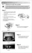
Install the Drum Unit Assembly
33
Load Paper into the Paper Cassette
33
Print a Test Page
34
For Windows ® Users
35
For Macintosh Users
39
Printing Methods
41
Printing from the Paper Cassette
41
Printing from Multi-Purpose Tray
41
Printing on Envelopes (Face up Printing)
43
Printing on Label, Transparency, Etc
44
Printing to the Face up Output Tray (Face up Printing)
47
Printing on both Sides of the Paper (Duplex Printing)
47
Manual Feed
49
Control Panel Operation
50
Data LED Indications
50
Panel Switches Functions
51
Go Switch
51
Job Cancel Switch
51
Reprint Switch
52
Switch
55
Set Switch
55
Back Switch
55
LCD Display
55
Backlights
56
Printer Status Messages
57
How to Use the Control Panel
58
Control Panel Setting Menu
59
Information
60
Paper
60
Quality
61
Setup
61
Print Menu
62
Network
66
Interface
66
Reset Menu
67
Set IP Address
67
5.5.10 about Emulation Modes
68
5.5.11 List of Factory Settings
68
Other Control Features
73
Sleep Mode
73
Inspection Mode
73
Network Board Operation
74
Installing the Network Board
74
Functions
76
LED Functions
76
Factory Default Setting
76
Chapter 3 Theory of Operation
78
Electronics
78
General Block Diagram
78
Main PCB Block Diagram
79
Main PCB
80
Asic
80
Rom
83
Flash ROM
84
Sdram
85
Optional RAM
87
PCI Bus
88
Eeprom
89
Reset Circuit
89
Engine I/O
90
1.3.10 Panel I/O
90
Engine PCB
92
BR-Net PCB
92
Power Supply
93
Low-Voltage Power Supply
93
High-Voltage Power Supply
94
Paper Transfer
97
Paper Supply
97
Paper Registration
97
Paper Eject
99
Duplex Printing
99
Sensors
100
Cover Sensors
100
Toner Sensors
100
DX Tray Sensor / DX Paper Size Sensor
102
Rear Cover Sensor
102
Cassette Sensor / Paper Empty Sensor
103
Paper Eject Sensor
103
Drum Unit
104
Photosensitive Drum
104
Primary Charger
104
Transfer Roller
104
Cleaner
104
Toner Cartridge
104
Print Process
104
Charging
104
Exposure Stage
105
Developing
106
Transfer
106
Fixing Stage
107
Chapter 4 Disassembly and Re-Assembly
108
Safety Precautions
108
Disassembly Flow
110
Disassembly Procedure
111
AC Cord
111
Drum Unit
111
Paper Cassette
112
Network Board (for HL-1870N Only)
119
Top Cover
120
DX Feed ASSY
124
Rear Cover
128
Rear Cover R & L / Side Cover R & L
130
MP Cover ASSY
132
Process Unit Cover ASSY
134
Laser Unit
135
Fixing Unit
136
Paper Pick-Up Roller ASSY
150
Feed MP Unit
151
Drive Unit
153
Low-Voltage Power Supply PCB ASSY
159
Main PCB ASSY
161
Fan Motor / Fan Motor 60
161
Base Plate
163
Engine PCB ASSY / High-Voltage Power Supply PCB ASSY
163
DX Sensor PCB ASSY
165
Toner Sensor PCB Unit (Light Reception)
166
Toner LED PCB Unit (Light Emission)
166
Paper Feed Roller ASSY
168
First Feed Roller ASSY
168
Exit Roller Unit
171
3.27 Harness Winding Form
174
Packing
175
Chapter 5 Periodic Maintenance
176
Consumable Parts
176
Drum Unit
176
Toner Cartridge
177
Periodical Replacement Parts
180
Periodical Cleaning
181
Cleaning the Printer Exterior
181
Cleaning the Drum Unit
181
Cleaning the Scanner Window
182
Cleaning the Electrical Terminals
183
Mtbf / Mttr
184
Chapter 6 Troubleshooting
185
Introduction
185
Initial Check
185
Warnings for Maintenance Work
186
Operator Calls & Service Calls
188
Operator Calls
188
Service Calls
190
Paper Problems
194
Paper Loading Problems
194
Paper Jams
195
Clearing Jammed Paper
196
Paper Jams
199
Causes & Countermeasures
206
Paper Feeding Problems
207
Software Setting Problems
210
Malfunctions
213
Image Defects
219
Image Defect Examples
219
Troubleshooting Image Defect
220
Location of Grounding Contacts
239
Drum Unit
239
Printer Body & Paper Cassette
239
Incorrect Printout
240
Network Problem
243
Installation Problem
243
Intermittent Problem
244
TCP/IP Troubleshooting
245
UNIX Troubleshooting
245
Windows NT/LAN Server (TCP/IP) Troubleshooting
246
Windows 95/98/Me (or Later) Peer to Peer Print (LPR) Troubleshooting
246
Windows 95/98/Me (or Later) Peer to Peer (HP Jetadmin Compatible Method) Troubleshooting
247
Windows 95/98/Me/Nt 4.0/2000 (or Later) Peer to Peer Print (Netbios) Troubleshooting
247
Internet Print (TCP/IP) Troubleshooting
247
Novell Netware Troubleshooting
248
Appletalk Troubleshooting
248
Apple TCP/IP Printing (System 8.6 or Later)
249
Web Browser Troubleshooting (TCP/IP)
249
Inspection Mode
250
Entering Inspection Mode
250
Sensor Check Mode
251
Chapter 7 Hidden Functions
254
Entering Hidden Function Menu Modes
254
Professional Menu Mode
255
Enabling and Disabling Professional Menu Mode
255
Function Table
263
Service Menu Mode
263
Entering the Service Menu Mode
263
Other Hidden Function Menus
266
Hidden Function Menus Enabled by Pressing Switch(Es) When Turning the Machine on
266
Drum Life Reset Function
266
Parts Life Reset Function
266
Connection Diagram, Hl-1850/1870N
268
Main Pcb Circuit Diagram, Hl-1850/1870N (1/6
269
Main Pcb Circuit Diagram, Hl-1850/1870N (2/6
270
Main Pcb Circuit Diagram, Hl-1850/1870N (3/6
271
Main Pcb Circuit Diagram, Hl-1850/1870N (4/6
272
Main Pcb Circuit Diagram, Hl-1850/1870N (5/6
273
Main Pcb Circuit Diagram, Hl-1850/1870N (6/6
274
Engine Pcb Circuit Diagram, Hl-1850/1870N (1/2
275
Engine Pcb Circuit Diagram, Hl-1850/1870N (2/2
276
Network Board Pcb Circuit Diagram, Hl-1850/1870N
277
Low-Voltage Power Supply Pcb Circuit Diagram (100V
278
Low-Voltage Power Supply Pcb Circuit Diagram (200V)
279
High-Voltage Power Supply Pcb Circuit Diagram
280
Serial No. Descriptions
281
Diameter / Circumference of Rollers
283
Print Speeds with Various Settings
284
How to Know Drum Unit Life & Page Counter
285
How to Use the Self-Diagnostics Tools
290
Printer Information
293
Nvram Default Value
294
Paper Cassette Information (for Europe Only
295
Guidelines for Lead Free Solder (Main Pcb Assy
296
How to Rewrite Hl-1850/1870N Flash Rom
299
Other manuals for Brother HL-1870N
Network User's Guide
149 pages
Technical Reference Guide
517 pages
Technical Reference Manual
450 pages
Driver Installation Guide
2 pages
Replacement Instruction
4 pages
Related product manuals
Brother HL-1800
4 pages
Brother HL-1850
517 pages
Brother HL-1110
73 pages
Brother HL-1202
79 pages
Brother HL-1200
79 pages
Brother HL-1112
79 pages
Brother HL-1430
95 pages
Brother HL-1050
517 pages
Brother HL-1440
2 pages
Brother HL-1210W
81 pages
Brother HL-1110E
2 pages
Brother HL-1470N
132 pages