3-60
Confidential
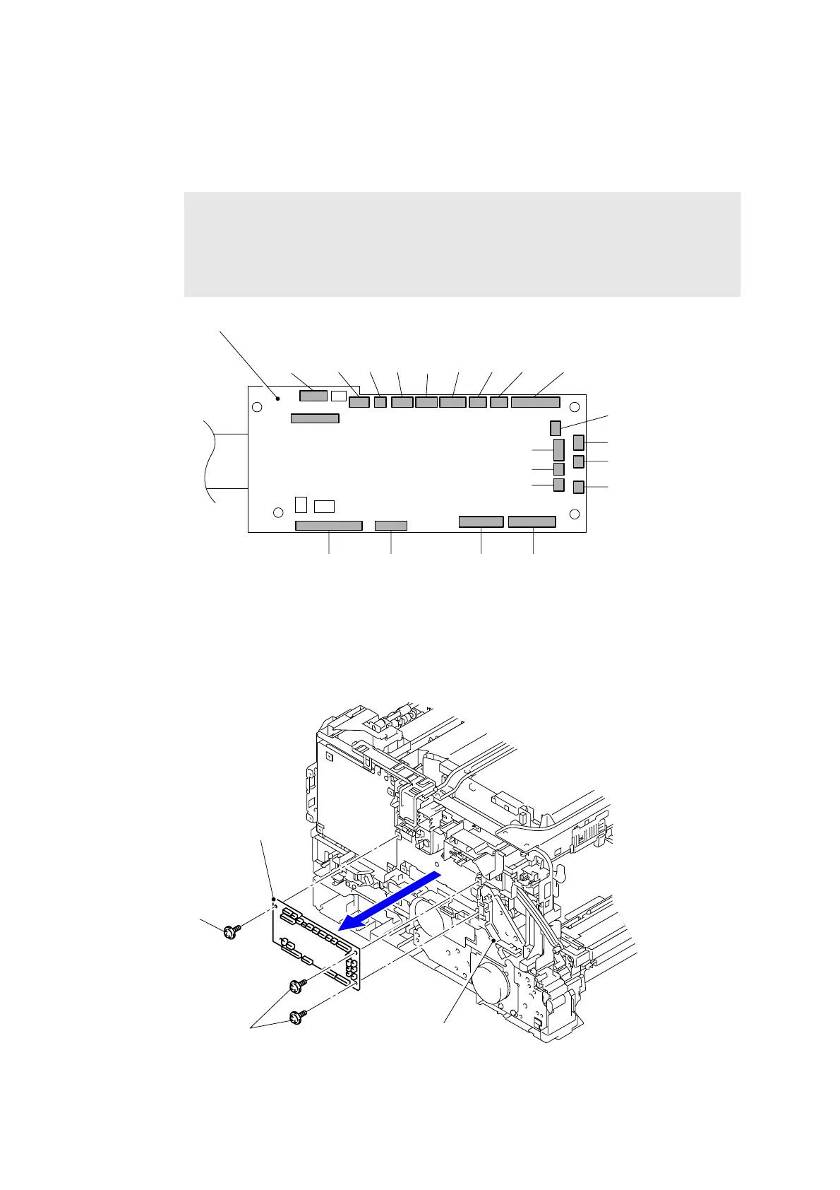
9.19 Engine PCB ASSY
(1) Disconnect the 17 Connectors (CN3, CN5, CN8, CN9, CN10, CN11, CN12, CN13, CN14,
CN16, CN17, CN18, CN19, CN20, CN21, CN22, and CN23) and four Flat cables (CN1,
CN2, CN15 and CN25).
Fig. 3-64
(2) Remove the three Taptite cup S M3x6 SR screws to remove the Engine PCB ASSY from
the Top drive ASSY.
Fig. 3-65
Note:
- After disconnecting flat cables, check that each cable is not damaged at its end or
shortcircuited.
- When connecting flat cables, do not insert them at an angle. After insertion, check
that the cables are not at an angle.
CN12
CN11
CN9
CN13
CN14
CN10
CN8
CN5 CN3 CN2 CN1
CN15
CN25 CN23 CN22 CN21 CN20 CN19 CN18 CN17 CN16
Engine PCB ASSY
Taptite cup S M3x6 SR
Top drive ASSY
Engine PCB ASSY
<Left side>
Taptite cup S
M3x6 SR

 Loading...