60
ZTKS0156 / Z31820 / Rev.: 03
Assembling
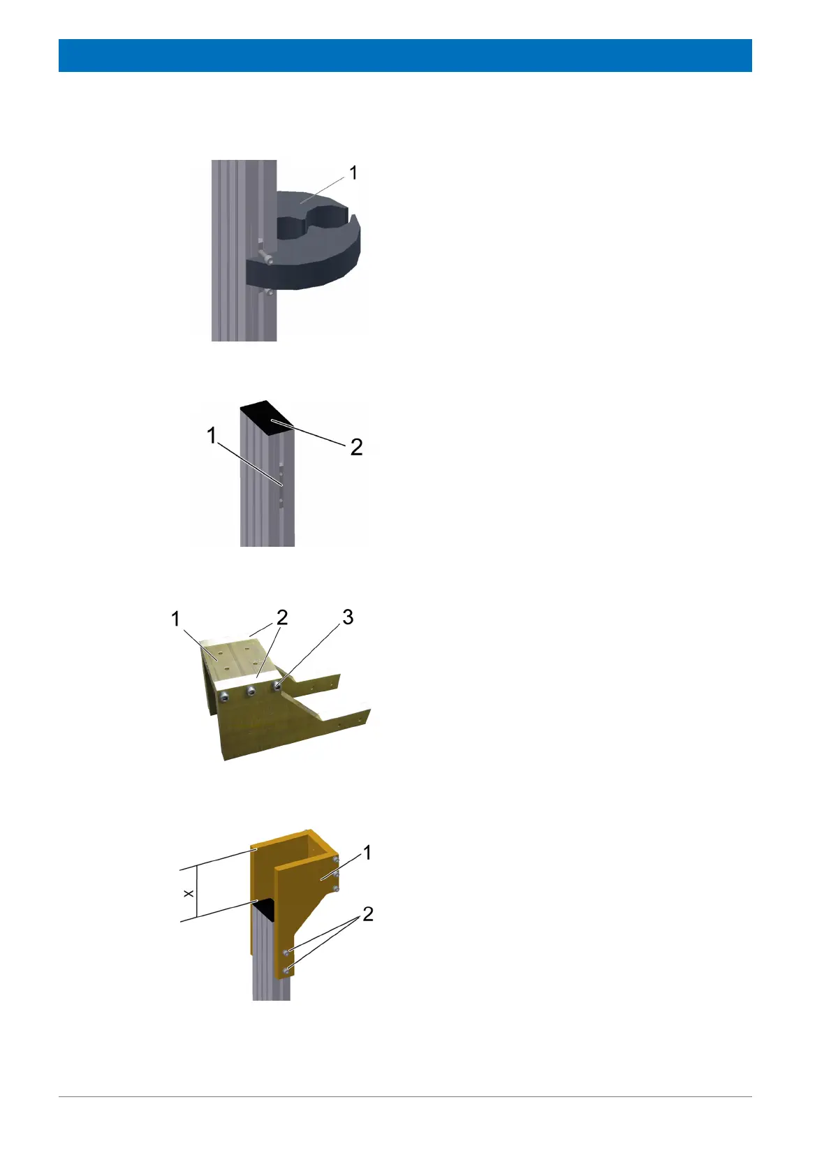
Figure 4.48: Mounting the Rotary Valve Column - step 10
21. Mount the flex line positioning disc (1) bet-
ween the two screws on the sliding block as
shown in the figure.
Figure 4.49: Mounting the Rotary Valve Column - step 11
22. Put two sliding blocks (1) into the tracks on
both sides of the profile rail.
23. Plug in the plastic cap (2) on the top side of
the profile.
Figure 4.50: Mounting the Rotary Valve Column - step 12
24. Assemble the front plate (1) to the two adap-
ter plates (2) using six M 8 x 35 screws with
washers (3) (torque 20 Nm).
Figure 4.51: Mounting the Rotary Valve Column - step 13
25. Mount the preassembled adapter (1) using
four M 8 x 35 screws with washers (2) to the
two sliding blocks.
26. Adjust it as shown in the figure.
400 R: X = 166 mm
500 R: X = 206 mm
27. Fix the four screws (torque 20 Nm).