59
ZTKS0156 / Z31820 / Rev.: 03
Assembling
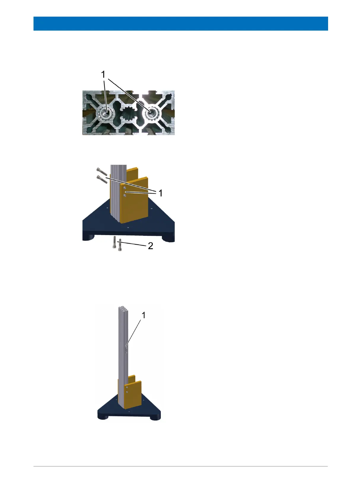
Figure 4.45: Mounting the Rotary Valve Column - step 7
10. Consider the bottom side of the profile with
the two thread inserts (1).
Figure 4.46: Mounting the Rotary Valve Column - step 8
11. Put two sliding blocks in each side track of
the profile rail.
12. Put the assembled profile rail in-between the
stand plates.
13. Attach the profile rail using four M 8 x 35
screws with washers (1) to the two stand
plates. Do not tighten these screws yet.
14. Fix the profile rail to the base plate with the
two M 8 x 35 screws with washers (2).
Tighten the screws (torque 20 Nm).
15. Tighten the four M 8 x 35 screws (1) of the
stand plates (torque 20 Nm).
16. Tighten the six M 12x35 screws of the stand
plates (torque 50 Nm).
Figure 4.47: Mounting the Rotary Valve Column - step 9
17. Put one sliding blocks (1) into the track at
one side of the profile rail.
18. Attach two M 8 x 35 screws in the sliding
block.
19. Adjust the sliding block on approximately
half of the profile rail.
20. Tighten the two M 8 x 35 screws.