66
ZTKS0156 / Z31820 / Rev.: 03
Assembling
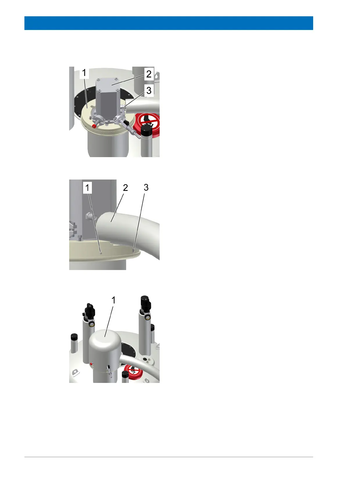
Figure 4.65: Mounting the Noise Protection Cover - step 1
29. Connect the connection line (3) to the cold
head (2) following the instructions given in
Figures 4.56-4.58 above.
Prevent any torque to the connection line
during tightening.
30. Loose the cup nut of the connection line with
1/4 rotation.
31. Assemble the two lower parts of the noise
protection cover (1) on the cold head turret.
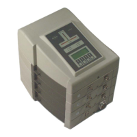
Figure 4.66: Mounting the Noise Protection Cover - step 2
32. Check the groove inside the lower part of
the noise protection cover is below the
connection line (2).
33. Attach the two M 4 screws (3) to assemble
the two lower parts of the noise protection
cover.
34. Fix the lower parts of the noise protection
cover with the four M 5 screws (1) to the
cold head turret.
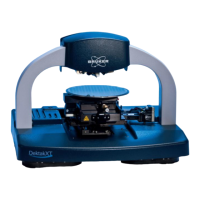
Figure 4.67: Mounting the Noise Protection Cover - step 3
35. Attach the noise protection cover (1) over
the cold head respecting the position.






 To Next Page