65
ZTKS0156 / Z31820 / Rev.: 03
Assembling
Figure 4.62: Mounting the Rotary Valve and Flex Lines - step 11
23. Put the noise protection cap on the top of
the rotary valve column.
Figure 4.63: Mounting the Rotary Valve and Flex Lines - step 12
24. Attach the insulation tube (1) to the connec-
tion line of the rotary valve.
Respect the orientation: put the female part
towards the rotary valve.
25. If necessary cut away 40 mm on the male
side of the insulation to allow free access to
the Aeroquip® coupling.
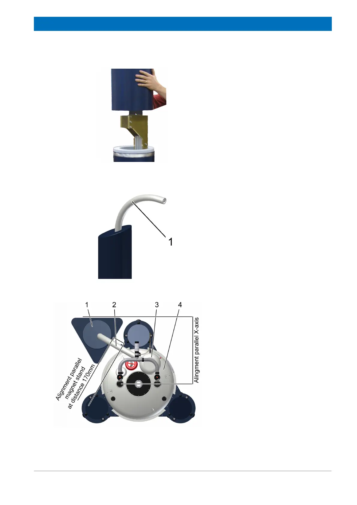
Figure 4.64: Mounting the Flex Lines and the Connection Line: Alignment
26. Align the rotary valve column (1)
relatively to the magnet stand and
the cryostat (4) as shown.
The connection line (2) between
rotary valve column (1) and cold
head (3) should not be stressed.
27. Remove the plastic cup nuts from
the spikes of the rotary valve
column.
28. Check the rotary valve column is
levelled horizontally. If necessary
adjust the levelling using the three
spikes of the rotary valve column.