74
ZTKS0156 / Z31820 / Rev.: 03
Assembling
Procedure cooling down the helium vessel:
1. Check the correct setting of the globes inside the quench valves (6).
2. Remove the connector and the tube to the stop valve.
3. Check the helium flow system is mounted like shown in the figure above.
4. Check the cold head (4) is in the lifted position (refer to ”Mounting the Cold Head”
on page 4-54).
5. Close the vacuum valve (refer to ”Removing the Vacuum Valve” on page 4-53)
and remove the vacuum pumping unit from the vacuum valve.
6. Connect the stop valve at the cold head flange with the vacuum pumping unit.
7. Apply a vacuum of 0.01 bar inside the cold head turret.
8. Pump and flush the cold head turret two times with warm helium gas.
9. Close the stop valve at the cold head flange.
10. Connect the stop valve at the cold head turret with a transportation dewar with warm
helium gas. Apply a pressure of 0.1 bar (1.5 PSI) at the transportation dewar.
11. Open the stop valve at the cold head flange.
12. Remove the plug on top of the helium fill-in turret.
13. Insert the precooling tube into the helium fill-in turret carefully. Check the precooling
tube is completely inserted. Check the O-ring sealing the precooling tube properly.
14. Connect the precooling tube (5) to a pressure gauge.
15. Connect the vacuum pumping unit at the one way valve (2).
16. Apply a vacuum of 0.01 bar inside the helium vessel.
17. Pump and flush the helium vessel one time at room temperature with warm nitrogen
gas to make sure that the helium vessel is dry before cooling down.
18. Connect the vacuum pumping unit to the vacuum valve and continue to generate
vacuum (refer to ”Generating the Vacuum” on page 4-52).
19. Insert the auxiliary shorting plug into the helium fill-in turret (right turret).
20. Remove the shorting plug out of the current lead turret (left turret).
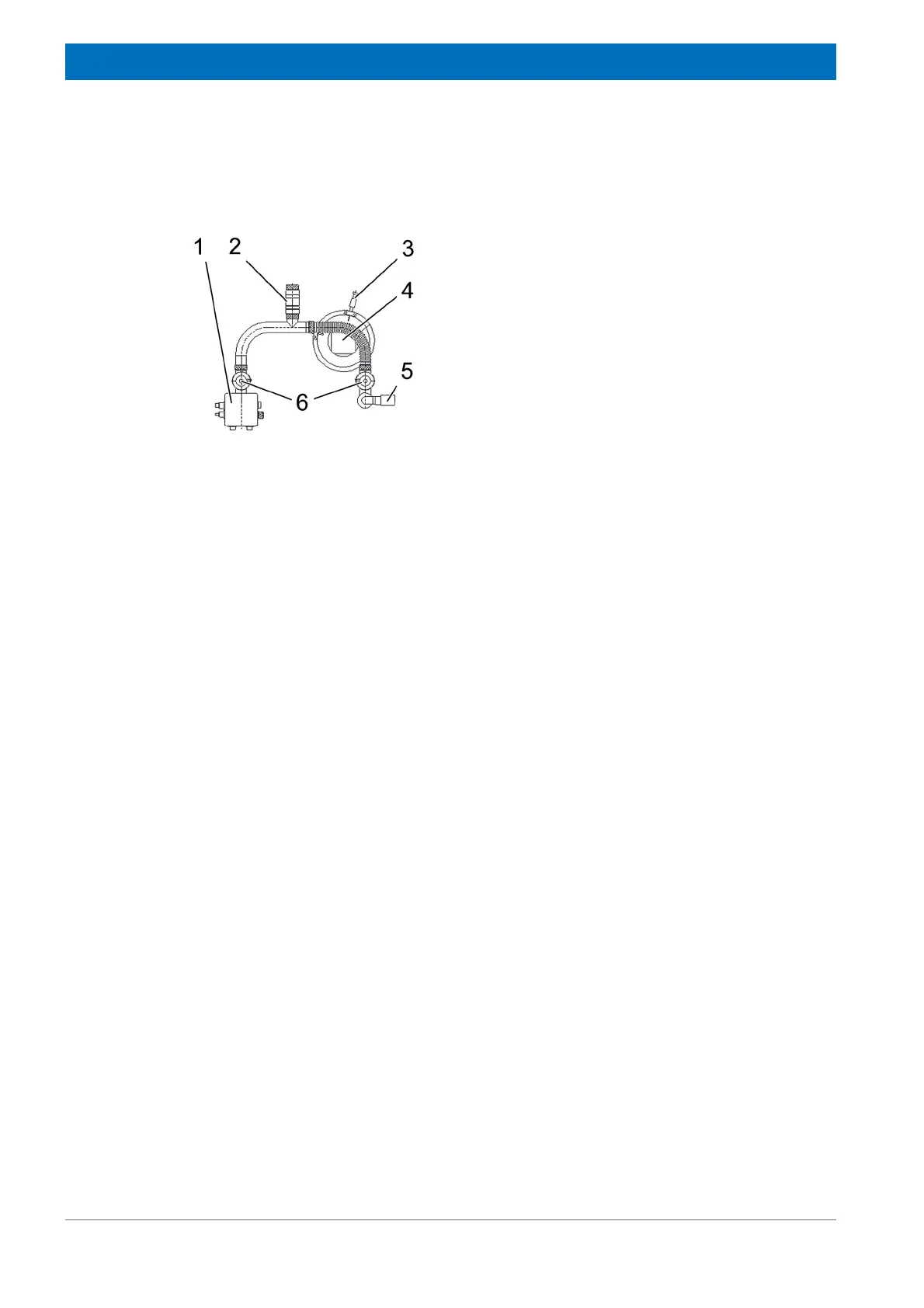
Figure 4.78: Helium Flow System during cool down
1 Current lead
2 One way valve
3 Stop valve
4 Cold Head
5 Precooling tube
6 Quench valves