20
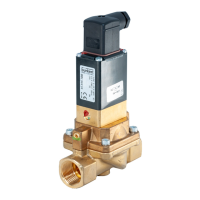
Option: Min. /max. stroke limitation
The actuators contain pre-tensioned springs that may derail or slip
on improper opening.
Actuators K-175 and L-225 shall only be opened in our factory •
or by the responsible distributor.
Interrupt the control air and fluid infeed before modifying the •
devices and reduce the pressure in the fluid system.
Interrupt supply of medium and empty valve housing.
→
Bring actuator into the upper piston position. →
The visibility hood must not be pressurized during attachment.
Therefore pressurize only the lower piston area via the lower •
control air connector using compressed air.
Unscrew transparent cap from actuator cover.
→
Screw out position indicator/spindle cap →
( yellow screw cap; see “Fig. 8: “) by hand.
Interrupt supply of control air.
→
Lightly grease spindle extension → ①
(silicone grease OKS 1110-0).
Screw spindle extension
→ ① (with Allan key WAF8) onto actuator
spindle (M16x1.5) and secure with Loctite 274.
Place guide spindle
→ ② over spindle extension ①.
Screw stop
→ ⑧ onto guide spindle ② and secure with
Loctite 274.
Stop length for Actuator K-175 (2012): 54.5 mm
Stop length for Actuator L-225 (2012): 44 mm
english